
Computer Drive User Manual
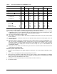
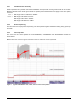
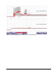
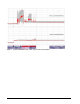
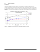
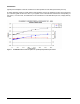
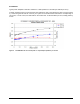
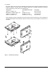
Table Of Contents
- 1.0 Scope 1
- 2.0 Standards, compliance and reference documents 3
- 3.0 General description 7
- 4.0 Performance characteristics 11
- 5.0 Reliability specifications 15
- 6.0 Physical/electrical specifications 23
- 6.1 AC power requirements 23
- 6.2 DC power requirements 23
- 6.3 Power dissipation 29
- 6.4 Environmental limits 32
- 6.4.1 Temperature 32
- 6.4.2 Relative humidity 32
- 6.4.3 Effective altitude (sea level) 33
- 6.4.4 Shock and vibration 33
- 6.4.5 Acoustics 35
- 6.4.6 Air cleanliness 35
- 6.4.7 Corrosive environment 35
- 6.4.8 European Union Restriction of Hazardous Substances (RoHS) Directive 36
- 6.4.9 China Restriction of Hazardous Substances (RoHS) Directive 36
- 6.4.10 Electromagnetic susceptibility 36
- 6.5 Mechanical specifications 37
- 7.0 Defect and error management 39
- 8.0 Installation 43
- 9.0 Interface requirements 47
- 9.1 FC-AL features 47
- 9.1.1 Fibre Channel link service frames 47
- 9.1.2 Fibre Channel task management functions 48
- 9.1.3 Fibre Channel task management responses 48
- 9.1.4 Fibre Channel port login 49
- 9.1.5 Fibre Channel port login accept 50
- 9.1.6 Fibre Channel Process Login 50
- 9.1.7 Fibre Channel Process Login Accept 51
- 9.1.8 Fibre Channel fabric login 51
- 9.1.9 Fibre Channel fabric accept login 52
- 9.1.10 Fibre Channel Arbitrated Loop options 53
- 9.2 Dual port support 53
- 9.3 SCSI commands supported 54
- 9.4 Miscellaneous operating features and conditions 63
- 9.5 FC-AL physical interface 64
- 9.5.1 Physical characteristics 64
- 9.5.2 Connector requirements 65
- 9.5.3 Electrical description 65
- 9.5.4 Pin descriptions 65
- 9.5.5 FC-AL transmitters and receivers 66
- 9.5.6 Power 67
- 9.5.7 Fault LED Out 67
- 9.5.8 Active LED Out 68
- 9.5.9 Enable port bypass signals 68
- 9.5.10 Motor start controls 68
- 9.5.11 SEL_6 through SEL_0 ID lines 69
- 9.5.12 Device control codes 71
- 9.6 Signal characteristics 71
- 9.1 FC-AL features 47
- 10.0 Seagate Technology support services 75
- 1.0 Scope
- 2.0 Standards, compliance and reference documents
- 3.0 General description
- 4.0 Performance characteristics
- 5.0 Reliability specifications
- 6.0 Physical/electrical specifications
- 6.1 AC power requirements
- 6.2 DC power requirements
- 6.3 Power dissipation
- 6.4 Environmental limits
- 6.4.1 Temperature
- 6.4.2 Relative humidity
- 6.4.3 Effective altitude (sea level)
- 6.4.4 Shock and vibration
- 6.4.5 Acoustics
- 6.4.6 Air cleanliness
- 6.4.7 Corrosive environment
- 6.4.8 European Union Restriction of Hazardous Substances (RoHS) Directive
- 6.4.9 China Restriction of Hazardous Substances (RoHS) Directive
- 6.4.10 Electromagnetic susceptibility
- 6.5 Mechanical specifications
- 7.0 Defect and error management
- 8.0 Installation
- 9.0 Interface requirements
- 9.1 FC-AL features
- 9.1.1 Fibre Channel link service frames
- 9.1.2 Fibre Channel task management functions
- 9.1.3 Fibre Channel task management responses
- 9.1.4 Fibre Channel port login
- 9.1.5 Fibre Channel port login accept
- 9.1.6 Fibre Channel Process Login
- 9.1.7 Fibre Channel Process Login Accept
- 9.1.8 Fibre Channel fabric login
- 9.1.9 Fibre Channel fabric accept login
- 9.1.10 Fibre Channel Arbitrated Loop options
- 9.2 Dual port support
- 9.3 SCSI commands supported
- 9.4 Miscellaneous operating features and conditions
- 9.5 FC-AL physical interface
- 9.5.1 Physical characteristics
- 9.5.2 Connector requirements
- 9.5.3 Electrical description
- 9.5.4 Pin descriptions
- 9.5.5 FC-AL transmitters and receivers
- 9.5.6 Power
- 9.5.7 Fault LED Out
- 9.5.8 Active LED Out
- 9.5.9 Enable port bypass signals
- 9.5.10 Motor start controls
- 9.5.11 SEL_6 through SEL_0 ID lines
- 9.5.12 Device control codes
- 9.6 Signal characteristics
- 9.1 FC-AL features
- 10.0 Seagate Technology support services
Cheetah NS 10K.2 FC Product Manual, Rev. B 25
Measured with average reading DC ammeter. Instantaneous +12V current peaks will exceed these values.
Power supply at nominal voltage. N (number of drives tested) = 6, 35 Degrees C ambient.
[4] For +12 V, a –10% tolerance is allowed during initial spindle start but must return to ±5% before reaching
10,000 RPM. The ±5% must be maintained after the drive signifies that its power-up sequence has been
completed and that the drive is able to accept selection by the host initiator.
[5] See +12V current profiles in Figures 1 and 2.
[6] This condition occurs when the Motor Start option is enabled and the drive has not yet received a Start
Motor command.
[7] See paragraph 6.2.1, "Conducted noise immunity." Specified voltage tolerance includes ripple, noise, and
transient response.
[8] Operating condition is defined as random 8 block reads at 320 s I/Os per second for ST3600002FC , 321
I/Os per second for ST3450802FC models, and 323 I/Os per second for ST3300602FC models. Current
and power specified at nominal voltages. Decreasing +5 volt supply by 5% increases 5 Volt current by
3.5%. Decreasing +12 volt supply by 5% increases 12 volt current by 2.5% (1.5% for ST3450802FC and
ST3300602FC models).
[9] During idle, the drive heads are relocated every 60 seconds to a random location within the band from
three-quarters to maximum track.
General DC power requirement notes.
1. Minimum current loading for each supply voltage is not less than 1.2% of the maximum operating current
shown.
2. The +5V and +12V supplies should employ separate ground returns.
3. Where power is provided to multiple drives from a common supply, careful consideration for individual
drive power requirements should be noted. Where multiple units are powered on simultaneously, the peak
starting current must be available to each device.
4. Parameters, other than spindle start, are measured after a 25-minute warm up.
5. No terminator power.
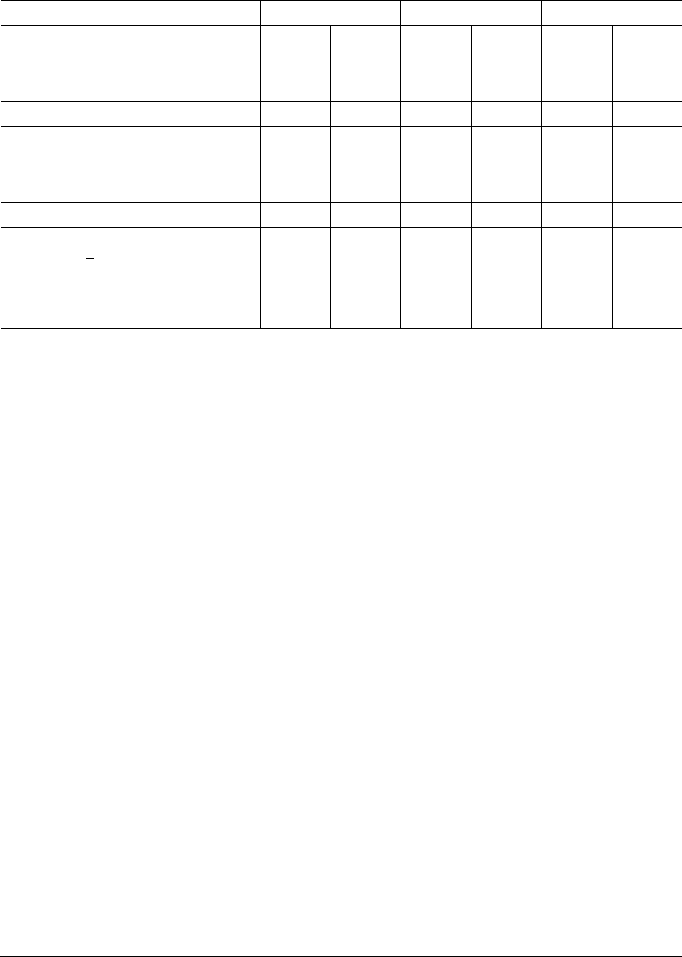
Table 4: DC power requirements for ST3300602FC model
1 Gbit 2 Gbit 4 Gbit
Notes (Amps) (Amps) (Amps) (Amps) (Amps) (Amps)
Voltage +5V +12V [4] +5V +12V [4] +5V +12V [4]
Regulation [5] ±5% ±5% [2] ±5% ±5% [2] ±5% ±5% [2]
Avg idle current DCX
[] [7] 0.36 0.31 0.38 0.30 0.40 0.30
Maximum starting current
(peak DC) DC 3σ [5] 0.44 1.94 0.46 1.95 0.63 1.95
(peak AC) AC 3σ [5] 0.84 3.98 0.74 3.64 1.02 3.66
Delayed motor start (max) DC 3σ [] [6] 0.44 0.04 0.46 0.04 0.48 0.04
Peak operating current:
Typical DCX [] [6] 0.38 0.60 0.40 0.60 0.42 0.60
Maximum DC 3σ [] 0.39 0.61 0.41 0.61 0.44 0.61
Maximum (peak) DC 3σ 1.00 2.38 1.02 2.44 1.04 2.40