
Computer Drive User Manual

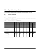
Table Of Contents
- 1.0 Scope 1
- 2.0 Standards, compliance and reference documents 3
- 3.0 General description 7
- 4.0 Performance characteristics 11
- 5.0 Reliability specifications 15
- 6.0 Physical/electrical specifications 23
- 6.1 AC power requirements 23
- 6.2 DC power requirements 23
- 6.3 Power dissipation 29
- 6.4 Environmental limits 32
- 6.4.1 Temperature 32
- 6.4.2 Relative humidity 32
- 6.4.3 Effective altitude (sea level) 33
- 6.4.4 Shock and vibration 33
- 6.4.5 Acoustics 35
- 6.4.6 Air cleanliness 35
- 6.4.7 Corrosive environment 35
- 6.4.8 European Union Restriction of Hazardous Substances (RoHS) Directive 36
- 6.4.9 China Restriction of Hazardous Substances (RoHS) Directive 36
- 6.4.10 Electromagnetic susceptibility 36
- 6.5 Mechanical specifications 37
- 7.0 Defect and error management 39
- 8.0 Installation 43
- 9.0 Interface requirements 47
- 9.1 FC-AL features 47
- 9.1.1 Fibre Channel link service frames 47
- 9.1.2 Fibre Channel task management functions 48
- 9.1.3 Fibre Channel task management responses 48
- 9.1.4 Fibre Channel port login 49
- 9.1.5 Fibre Channel port login accept 50
- 9.1.6 Fibre Channel Process Login 50
- 9.1.7 Fibre Channel Process Login Accept 51
- 9.1.8 Fibre Channel fabric login 51
- 9.1.9 Fibre Channel fabric accept login 52
- 9.1.10 Fibre Channel Arbitrated Loop options 53
- 9.2 Dual port support 53
- 9.3 SCSI commands supported 54
- 9.4 Miscellaneous operating features and conditions 63
- 9.5 FC-AL physical interface 64
- 9.5.1 Physical characteristics 64
- 9.5.2 Connector requirements 65
- 9.5.3 Electrical description 65
- 9.5.4 Pin descriptions 65
- 9.5.5 FC-AL transmitters and receivers 66
- 9.5.6 Power 67
- 9.5.7 Fault LED Out 67
- 9.5.8 Active LED Out 68
- 9.5.9 Enable port bypass signals 68
- 9.5.10 Motor start controls 68
- 9.5.11 SEL_6 through SEL_0 ID lines 69
- 9.5.12 Device control codes 71
- 9.6 Signal characteristics 71
- 9.1 FC-AL features 47
- 10.0 Seagate Technology support services 75
- 1.0 Scope
- 2.0 Standards, compliance and reference documents
- 3.0 General description
- 4.0 Performance characteristics
- 5.0 Reliability specifications
- 6.0 Physical/electrical specifications
- 6.1 AC power requirements
- 6.2 DC power requirements
- 6.3 Power dissipation
- 6.4 Environmental limits
- 6.4.1 Temperature
- 6.4.2 Relative humidity
- 6.4.3 Effective altitude (sea level)
- 6.4.4 Shock and vibration
- 6.4.5 Acoustics
- 6.4.6 Air cleanliness
- 6.4.7 Corrosive environment
- 6.4.8 European Union Restriction of Hazardous Substances (RoHS) Directive
- 6.4.9 China Restriction of Hazardous Substances (RoHS) Directive
- 6.4.10 Electromagnetic susceptibility
- 6.5 Mechanical specifications
- 7.0 Defect and error management
- 8.0 Installation
- 9.0 Interface requirements
- 9.1 FC-AL features
- 9.1.1 Fibre Channel link service frames
- 9.1.2 Fibre Channel task management functions
- 9.1.3 Fibre Channel task management responses
- 9.1.4 Fibre Channel port login
- 9.1.5 Fibre Channel port login accept
- 9.1.6 Fibre Channel Process Login
- 9.1.7 Fibre Channel Process Login Accept
- 9.1.8 Fibre Channel fabric login
- 9.1.9 Fibre Channel fabric accept login
- 9.1.10 Fibre Channel Arbitrated Loop options
- 9.2 Dual port support
- 9.3 SCSI commands supported
- 9.4 Miscellaneous operating features and conditions
- 9.5 FC-AL physical interface
- 9.5.1 Physical characteristics
- 9.5.2 Connector requirements
- 9.5.3 Electrical description
- 9.5.4 Pin descriptions
- 9.5.5 FC-AL transmitters and receivers
- 9.5.6 Power
- 9.5.7 Fault LED Out
- 9.5.8 Active LED Out
- 9.5.9 Enable port bypass signals
- 9.5.10 Motor start controls
- 9.5.11 SEL_6 through SEL_0 ID lines
- 9.5.12 Device control codes
- 9.6 Signal characteristics
- 9.1 FC-AL features
- 10.0 Seagate Technology support services

18 Cheetah NS 10K.2 FC Product Manual, Rev. B
Reporting control
Reporting is controlled by the MRIE bits in the Informational Exceptions Control mode page (1Ch). Subject to
the reporting method, the firmware will issue to the host an 01-5Dxx sense code. The error code is preserved
through bus resets and power cycles.
Determining rate
S.M.A.R.T. monitors the rate at which errors occur and signals a predictive failure if the rate of degraded errors
increases to an unacceptable level. To determine rate, error events are logged and compared to the number of
total operations for a given attribute. The interval defines the number of operations over which to measure the
rate. The counter that keeps track of the current number of operations is referred to as the Interval Counter.
S.M.A.R.T. measures error rates. All errors for each monitored attribute are recorded. A counter keeps track of
the number of errors for the current interval. This counter is referred to as the Failure Counter.
Error rate is the number of errors per operation. The algorithm that S.M.A.R.T. uses to record rates of error is to
set thresholds for the number of errors and their interval. If the number of errors exceeds the threshold before
the interval expires, the error rate is considered to be unacceptable. If the number of errors does not exceed
the threshold before the interval expires, the error rate is considered to be acceptable. In either case, the inter-
val and failure counters are reset and the process starts over.
Predictive failures
S.M.A.R.T. signals predictive failures when the drive is performing unacceptably for a period of time. The firm-
ware keeps a running count of the number of times the error rate for each attribute is unacceptable. To accom-
plish this, a counter is incremented each time the error rate is unacceptable and decremented (not to exceed
zero) whenever the error rate is acceptable. If the counter continually increments such that it reaches the pre-
dictive threshold, a predictive failure is signaled. This counter is referred to as the Failure History Counter.
There is a separate Failure History Counter for each attribute.
5.2.5 Thermal monitor
Cheetah NS 10K.2 FC drives implement a temperature warning system which:
1. Signals the host if the temperature exceeds a value which would threaten the drive.
2. Signals the host if the temperature exceeds a user-specified value.
3. Saves a S.M.A.R.T. data frame on the drive which exceeds the threatening temperature value.
A temperature sensor monitors the drive temperature and issues a warning over the interface when the tem-
perature exceeds a set threshold. The temperature is measured at power-up and then at ten-minute intervals
after power-up.
The thermal monitor system generates a warning code of 01-0B01 when the temperature exceeds the speci-
fied limit in compliance with the SCSI standard. The drive temperature is reported in the FRU code field of
mode sense data. You can use this information to determine if the warning is due to the temperature exceeding
the drive threatening temperature or the user-specified temperature.
This feature is controlled by the Enable Warning (EWasc) bit, and the reporting mechanism is controlled by the
Method of Reporting Informational Exceptions field (MRIE) on the Informational Exceptions Control (IEC)
mode page (1Ch).
The current algorithm implements two temperature trip points. The first trip point is set at 68°C which is the
maximum temperature limit according to the drive specification. The second trip point is user-selectable using
the Log Select command. The reference temperature parameter in the temperature log page (see Table 1) can