
Computer Drive User Manual

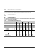
Table Of Contents
- 1.0 Scope 1
- 2.0 Standards, compliance and reference documents 3
- 3.0 General description 7
- 4.0 Performance characteristics 11
- 5.0 Reliability specifications 15
- 6.0 Physical/electrical specifications 23
- 6.1 AC power requirements 23
- 6.2 DC power requirements 23
- 6.3 Power dissipation 29
- 6.4 Environmental limits 32
- 6.4.1 Temperature 32
- 6.4.2 Relative humidity 32
- 6.4.3 Effective altitude (sea level) 33
- 6.4.4 Shock and vibration 33
- 6.4.5 Acoustics 35
- 6.4.6 Air cleanliness 35
- 6.4.7 Corrosive environment 35
- 6.4.8 European Union Restriction of Hazardous Substances (RoHS) Directive 36
- 6.4.9 China Restriction of Hazardous Substances (RoHS) Directive 36
- 6.4.10 Electromagnetic susceptibility 36
- 6.5 Mechanical specifications 37
- 7.0 Defect and error management 39
- 8.0 Installation 43
- 9.0 Interface requirements 47
- 9.1 FC-AL features 47
- 9.1.1 Fibre Channel link service frames 47
- 9.1.2 Fibre Channel task management functions 48
- 9.1.3 Fibre Channel task management responses 48
- 9.1.4 Fibre Channel port login 49
- 9.1.5 Fibre Channel port login accept 50
- 9.1.6 Fibre Channel Process Login 50
- 9.1.7 Fibre Channel Process Login Accept 51
- 9.1.8 Fibre Channel fabric login 51
- 9.1.9 Fibre Channel fabric accept login 52
- 9.1.10 Fibre Channel Arbitrated Loop options 53
- 9.2 Dual port support 53
- 9.3 SCSI commands supported 54
- 9.4 Miscellaneous operating features and conditions 63
- 9.5 FC-AL physical interface 64
- 9.5.1 Physical characteristics 64
- 9.5.2 Connector requirements 65
- 9.5.3 Electrical description 65
- 9.5.4 Pin descriptions 65
- 9.5.5 FC-AL transmitters and receivers 66
- 9.5.6 Power 67
- 9.5.7 Fault LED Out 67
- 9.5.8 Active LED Out 68
- 9.5.9 Enable port bypass signals 68
- 9.5.10 Motor start controls 68
- 9.5.11 SEL_6 through SEL_0 ID lines 69
- 9.5.12 Device control codes 71
- 9.6 Signal characteristics 71
- 9.1 FC-AL features 47
- 10.0 Seagate Technology support services 75
- 1.0 Scope
- 2.0 Standards, compliance and reference documents
- 3.0 General description
- 4.0 Performance characteristics
- 5.0 Reliability specifications
- 6.0 Physical/electrical specifications
- 6.1 AC power requirements
- 6.2 DC power requirements
- 6.3 Power dissipation
- 6.4 Environmental limits
- 6.4.1 Temperature
- 6.4.2 Relative humidity
- 6.4.3 Effective altitude (sea level)
- 6.4.4 Shock and vibration
- 6.4.5 Acoustics
- 6.4.6 Air cleanliness
- 6.4.7 Corrosive environment
- 6.4.8 European Union Restriction of Hazardous Substances (RoHS) Directive
- 6.4.9 China Restriction of Hazardous Substances (RoHS) Directive
- 6.4.10 Electromagnetic susceptibility
- 6.5 Mechanical specifications
- 7.0 Defect and error management
- 8.0 Installation
- 9.0 Interface requirements
- 9.1 FC-AL features
- 9.1.1 Fibre Channel link service frames
- 9.1.2 Fibre Channel task management functions
- 9.1.3 Fibre Channel task management responses
- 9.1.4 Fibre Channel port login
- 9.1.5 Fibre Channel port login accept
- 9.1.6 Fibre Channel Process Login
- 9.1.7 Fibre Channel Process Login Accept
- 9.1.8 Fibre Channel fabric login
- 9.1.9 Fibre Channel fabric accept login
- 9.1.10 Fibre Channel Arbitrated Loop options
- 9.2 Dual port support
- 9.3 SCSI commands supported
- 9.4 Miscellaneous operating features and conditions
- 9.5 FC-AL physical interface
- 9.5.1 Physical characteristics
- 9.5.2 Connector requirements
- 9.5.3 Electrical description
- 9.5.4 Pin descriptions
- 9.5.5 FC-AL transmitters and receivers
- 9.5.6 Power
- 9.5.7 Fault LED Out
- 9.5.8 Active LED Out
- 9.5.9 Enable port bypass signals
- 9.5.10 Motor start controls
- 9.5.11 SEL_6 through SEL_0 ID lines
- 9.5.12 Device control codes
- 9.6 Signal characteristics
- 9.1 FC-AL features
- 10.0 Seagate Technology support services

Cheetah NS 10K.2 FC Product Manual, Rev. B 17
The Pass-through state is disabled while the drive performs self test of the FC interface. The control line for an
external port bypass circuit remains in the Enable Bypass state while self test is running. If the bypass circuit is
present, loop operation may continue. If the bypass circuit is not present, loop operation will be halted while the
self test of the FC interface runs.
When the self test completes successfully, the control line to the bypass circuit is disabled and the drive enters
the FC-AL Initializing state. The receiver on the next device in the loop must synchronize to output of the newly
inserted drive.
If the self-test fails, the control line to the bypass circuit remains in the Enable Bypass state.
Note. It is the responsibility of the systems integrator to assure that no temperature, energy, voltage haz-
ard, or ESD potential hazard is presented during the hot connect/disconnect operation. Discharge
the static electricity from the drive carrier prior to inserting it into the system.
Caution. The drive motor must come to a complete stop prior to changing the plane of operation. This time is
required to insure data integrity.
5.2.4 S.M.A.R.T.
S.M.A.R.T. is an acronym for Self-Monitoring Analysis and Reporting Technology. This technology is intended
to recognize conditions that indicate imminent drive failure and is designed to provide sufficient warning of a
failure to allow you to back up the data before an actual failure occurs.
Note. The drive’s firmware monitors specific attributes for degradation over time but can’t predict instanta-
neous drive failures.
Each monitored attribute has been selected to monitor a specific set of failure conditions in the operating per-
formance of the drive and the thresholds are optimized to minimize “false” and “failed” predictions.
Controlling S.M.A.R.T.
The operating mode of S.M.A.R.T. is controlled by the DEXCPT and PERF bits on the Informational Exceptions
Control mode page (1Ch). Use the DEXCPT bit to enable or disable the S.M.A.R.T. feature. Setting the DEX-
CPT bit disables all S.M.A.R.T. functions. When enabled, S.M.A.R.T. collects on-line data as the drive performs
normal read and write operations. When the PERF bit is set, the drive is considered to be in “On-line Mode
Only” and will not perform off-line functions.
You can measure off-line attributes and force the drive to save the data by using the Rezero Unit command.
Forcing S.M.A.R.T. resets the timer so that the next scheduled interrupt is in two hours.
You can interrogate the drive through the host to determine the time remaining before the next scheduled mea-
surement and data logging process occurs. To accomplish this, issue a Log Sense command to log page 0x3E.
This allows you to control when S.M.A.R.T. interruptions occur. Forcing S.M.A.R.T. with the RTZ command
resets the timer.
Performance impact
S.M.A.R.T. attribute data is saved to the disk so that the events that caused a predictive failure can be recre-
ated. The drive measures and saves parameters once every two hours subject to an idle period on the FC-AL
bus. The process of measuring off-line attribute data and saving data to the disk is uninterruptable. The maxi-
mum on-line only processing delay is summarized below:
Maximum processing delay
On-line only delay
DEXCPT = 0, PERF = 1
Fully-enabled delay
DEXCPT = 0, PERF = 0
S.M.A.R.T. delay times
42 milliseconds
163 milliseconds