
Computer Drive User Manual

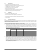
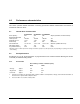
Table Of Contents
- 1.0 Scope 1
- 2.0 Standards, compliance and reference documents 3
- 3.0 General description 7
- 4.0 Performance characteristics 11
- 5.0 Reliability specifications 15
- 6.0 Physical/electrical specifications 23
- 6.1 AC power requirements 23
- 6.2 DC power requirements 23
- 6.3 Power dissipation 29
- 6.4 Environmental limits 32
- 6.4.1 Temperature 32
- 6.4.2 Relative humidity 32
- 6.4.3 Effective altitude (sea level) 33
- 6.4.4 Shock and vibration 33
- 6.4.5 Acoustics 35
- 6.4.6 Air cleanliness 35
- 6.4.7 Corrosive environment 35
- 6.4.8 European Union Restriction of Hazardous Substances (RoHS) Directive 36
- 6.4.9 China Restriction of Hazardous Substances (RoHS) Directive 36
- 6.4.10 Electromagnetic susceptibility 36
- 6.5 Mechanical specifications 37
- 7.0 Defect and error management 39
- 8.0 Installation 43
- 9.0 Interface requirements 47
- 9.1 FC-AL features 47
- 9.1.1 Fibre Channel link service frames 47
- 9.1.2 Fibre Channel task management functions 48
- 9.1.3 Fibre Channel task management responses 48
- 9.1.4 Fibre Channel port login 49
- 9.1.5 Fibre Channel port login accept 50
- 9.1.6 Fibre Channel Process Login 50
- 9.1.7 Fibre Channel Process Login Accept 51
- 9.1.8 Fibre Channel fabric login 51
- 9.1.9 Fibre Channel fabric accept login 52
- 9.1.10 Fibre Channel Arbitrated Loop options 53
- 9.2 Dual port support 53
- 9.3 SCSI commands supported 54
- 9.4 Miscellaneous operating features and conditions 63
- 9.5 FC-AL physical interface 64
- 9.5.1 Physical characteristics 64
- 9.5.2 Connector requirements 65
- 9.5.3 Electrical description 65
- 9.5.4 Pin descriptions 65
- 9.5.5 FC-AL transmitters and receivers 66
- 9.5.6 Power 67
- 9.5.7 Fault LED Out 67
- 9.5.8 Active LED Out 68
- 9.5.9 Enable port bypass signals 68
- 9.5.10 Motor start controls 68
- 9.5.11 SEL_6 through SEL_0 ID lines 69
- 9.5.12 Device control codes 71
- 9.6 Signal characteristics 71
- 9.1 FC-AL features 47
- 10.0 Seagate Technology support services 75
- 1.0 Scope
- 2.0 Standards, compliance and reference documents
- 3.0 General description
- 4.0 Performance characteristics
- 5.0 Reliability specifications
- 6.0 Physical/electrical specifications
- 6.1 AC power requirements
- 6.2 DC power requirements
- 6.3 Power dissipation
- 6.4 Environmental limits
- 6.4.1 Temperature
- 6.4.2 Relative humidity
- 6.4.3 Effective altitude (sea level)
- 6.4.4 Shock and vibration
- 6.4.5 Acoustics
- 6.4.6 Air cleanliness
- 6.4.7 Corrosive environment
- 6.4.8 European Union Restriction of Hazardous Substances (RoHS) Directive
- 6.4.9 China Restriction of Hazardous Substances (RoHS) Directive
- 6.4.10 Electromagnetic susceptibility
- 6.5 Mechanical specifications
- 7.0 Defect and error management
- 8.0 Installation
- 9.0 Interface requirements
- 9.1 FC-AL features
- 9.1.1 Fibre Channel link service frames
- 9.1.2 Fibre Channel task management functions
- 9.1.3 Fibre Channel task management responses
- 9.1.4 Fibre Channel port login
- 9.1.5 Fibre Channel port login accept
- 9.1.6 Fibre Channel Process Login
- 9.1.7 Fibre Channel Process Login Accept
- 9.1.8 Fibre Channel fabric login
- 9.1.9 Fibre Channel fabric accept login
- 9.1.10 Fibre Channel Arbitrated Loop options
- 9.2 Dual port support
- 9.3 SCSI commands supported
- 9.4 Miscellaneous operating features and conditions
- 9.5 FC-AL physical interface
- 9.5.1 Physical characteristics
- 9.5.2 Connector requirements
- 9.5.3 Electrical description
- 9.5.4 Pin descriptions
- 9.5.5 FC-AL transmitters and receivers
- 9.5.6 Power
- 9.5.7 Fault LED Out
- 9.5.8 Active LED Out
- 9.5.9 Enable port bypass signals
- 9.5.10 Motor start controls
- 9.5.11 SEL_6 through SEL_0 ID lines
- 9.5.12 Device control codes
- 9.6 Signal characteristics
- 9.1 FC-AL features
- 10.0 Seagate Technology support services

12 Cheetah NS 10K.2 FC Product Manual, Rev. B
4.2.2 Format command execution time (minutes)
ST3600002FC ST3450802FC ST3300602FC
Maximum (with verify) 182 129 83
Maximum (without verify) 101 68 43
Execution time measured from receipt of the last byte of the
Command Descriptor Block (CDB) to the request
for a Status Byte Transfer to the Initiator (excluding connect/disconnect).
When changing sector sizes, the format times shown above may need to be increased by 30 minutes.
4.2.3 General performance characteristics
Sustainable disk transfer rate*:
Minimum 82 Mbytes/sec
Maximum 150 Mbytes/sec
Fibre Channel Interface maximum instantaneous transfer rate 800 Mbytes/sec* per port
(dual port = 1600 Mbytes/sec*)
Logical block sizes
Default is 512-byte data blocks
Sector sizes variable to 512, 520, 524 and 528 bytes.
Read/write consecutive sectors on a track Ye s
Flaw reallocation performance impact (for flaws reallocated at format time
using the spare sectors per sparing zone reallocation scheme.)
Negligible
*Assumes no errors and no relocated logical blocks. Rate measured
from the start of the first logical block transfer to or
from the host.
4.3 Start/stop time
The drive accepts the commands listed in the Fibre Channel Interface Manual less than 3 seconds after DC
power has been applied.
If the drive receives a NOTIFY (ENABLE SPINUP) primitive through either port and has not received a START
STOP UNIT command with the START bit equal to 0, the drive becomes ready for normal operations within 30
seconds (excluding the error recovery procedure).
If the drive receives a START STOP UNIT command with the START bit equal to 0 before receiving a NOTIFY
(ENABLE SPINUP) primitive, the drive waits for a START STOP UNIT command with the START bit equal to 1.
After receiving a START STOP UNIT command with the START bit equal to 1, the drive waits for a NOTIFY
(ENABLE SPINUP) primitive. After receiving a NOTIFY (ENABLE SPINUP) primitive through either port, the
drive becomes ready for normal operations within 30 seconds (excluding the error recovery procedure).
If the drive receives a START STOP UNIT command with the START bit and IMMED bit equal to 1 and does
not receive a NOTIFY (ENABLE SPINUP) primitive within 5 seconds, the drive fails the START STOP UNIT
command.
The START STOP UNIT command may be used to command the drive to stop the spindle. Stop time is 30 sec-
onds (maximum) from removal of DC power.
There is no power control switch on the drive.