ARS-2017E Mirror Smart Ultra160 User’s Manual Version: 1.0 Copyright © 2004 ACARD Technology Corp.
Copyright and Trademarks The information in this manual is subject to change without prior notice and does not represent a commitment on the part of the vendor, who assumes no liability or responsibility for any errors that may appear in this manual. ACARD and SCSIDE® are the trademarks of ACARD Technology Corp. IBM is the trademark of International Business Machine Corporation. Microsoft and the Windows Logo are the registered trademarks, and Windows is the trademark of Microsoft Corporation.
Table of Contents Chapter 1 About SCSIDE® ................................................................... 4 1.1 Revolutionary Technology ..................................... 4 1.2 SCSIDE® Design ...................................................... 5 Chapter 2 Introduction ...................................... 6 2.1 2.2 2.3 2.4 2.5 2.6 2.7 2.8 Overview .................................................................. 6 Features ....................................................................
ARS-2017E Manual Chapter 1 About SCSIDE® 1.1 Revolutionary Technology SCSIDE ® is a revolutionary technology developed by ACARD Technology Corp. It can transform IDE data into SCSI type, and save the expenditures. Through this technology any inexpensive IDE device can have high-performance SCSI applications. The following examples are some of the SCSIDE ® applications. 1. To transform an IDE hard drive into an external SCSI one for notebook and desktop PC users to back up data. 2.
ARS-2017E Manual 1.2 SCSIDE® Design The objectives of SCSIDE ® design are described as follows: 1. Save the expenditures of SCSI by using an inexpensive IDE device. 2. Create applications like SCSI CD-ROM and high speed SCSI DVD-ROM. 3. Apply ”plug and play” to the transformation of IDE device to SCSI one. It is not necessary to install a driver. Welcome to be a new member of SCSIDE ® and have a good time.
ARS-2017E Manual Chapter 2 Introduction 2.1 Overview ARS-2017E is an Ultra 160 SCSI-to-IDE RAID 1 mirroring subsystem. It has an LCD panel for you to set, monitor easily and adopts ACARD’s SCSIDE ® technology, so you can connect it with the inexpensive ATA 133/100/66 hard drives to achieve those SCSI advantages like multitasking, daisy chain and highly efficient data processing.
ARS-2017E Manual 2.2 Features n n n n n n n n n n n n n n n n Supports RAID 1 mirroring Supports real time rebuilding (up to 2.5GB per minute) Supports hot swap Supports multitasking LCD panel for setting, monitoring system and hard drive status Supports ROC SCSIDE ® engine Minimized CPU utilization Supports ATA 133/100/66 hard drives Supports “Big Drive” technology (a hard drive over 137GB) Patented “Dr.
ARS-2017E Manual 2.5 Dimension & Temperature Dimension Length: 28cm / Width: 18cm / Height: 19cm Temperature –20°C ~ 70°C (–4°F ~ 158°F) for non-operation 0°C ~ 50°C (32°F ~ 122°F) for operation (not condensed) 2.6 Package Open the package of ARS-2017E, and check its contents. If there is anything missing, contact your distributor.
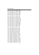
ARS-2017E Manual Step 9: Power on the PC and ARS-2017E. Step 10: After powering on, the SCSI card will detect a hard drive named Mirror Smart. Before using, partition and format if it is new. 2.8 HDD Compatibility ARS-2017E is particularly designed for DMA hard drives. It fully supports the following brands of DMA 133/100/66 hard drives. It is recommended to set the jumper as “Master/Single” or “Cable Select” in order to quicken the start of a hard drive.
ARS-2017E Manual Maxtor DiamondMax Plus9 6Y200P0 200GB Maxtor DiamondMax Plus9 6Y160P0 160GB Maxtor DiamondMax Plus9 6Y160J0 160GB Maxtor DiamondMax Plus9 6Y120L0 120GB Maxtor DiamondMax Plus9 6Y120P0 120GB Maxtor DiamondMax Plus9 6Y080L0 80GB Maxtor DiamondMax Plus9 6Y080P0 80GB Maxtor DiamondMax Plus9 6Y060L0 60GB Maxtor DiamondMax Plus16 4R160J0 160GB Maxtor DiamondMax Plus16 4R160L0 160GB Maxtor DiamondMax Plus16 4R120L0 120GB Maxtor DiamondMax Plus16 4R080L0 80GB Maxtor DiamondMax Plus16 4R080J0 80GB M
ARS-2017E Manual Hitachi 60GXP IC35L060AVER07 61.49GB Hitachi 60GXP IC35L040AVER07 41.17GB Hitachi 60GXP IC35L030AVER07 30.73GB Hitachi 75GXP DTLA-307075 76.86GB Hitachi 75GXP DTLA-307060 61.49GB Hitachi 75GXP DTLA-307045 46.11GB Hitachi 75GXP DTLA-307030 30.73GB Hitachi 40GV DTLA-305040 41.17 GB Hitachi 40GV DTLA-305030 30.
ARS-2017E Manual Chapter 3 The Control Panel 3.1 LCD Panel There are 4 buttons on the LCD panel of ARS-2017E. ▲ : to scroll up the functions or menus. ▼ : to scroll down the functions or menus. ENT : to confirm a setting and enter the selected function. ESC : to cancel a setting and return to the previous layer of functions. Pressing ESC for more than 2 seconds will let the system return to standby mode. 3.
ARS-2017E Manual 1: SYSTEM INFO 1.1: Mirror info 1.2: Disk0 info 1.3: Disk1 info 1.4: Health info 1.1.1: 1.2.1: 1.3.1: 1.4.1: Vendor ID Model ID Vendor ID Model ID Vendor ID Model ID Disk0 temp. Fan rpm 1.1.2: 1.2.2: 1.3.2: 1.4.2: Revision Revision Revision Disk1 temp. SCSI max speed IDE max speed IDE max speed Fan rpm 1.1.3: 1.2.3: 1.3.3: Status Capacity Status Capacity Status Capacity 1.4.3: System temp. Fan rpm 2: SETUP 2.1: Mirror Opt. 2.2: Health Opt. 2.
ARS-2017E Manual 3: ADVANCED SETUP 3.1: Mirror size 3.2: Compare 3.3: Scan disk0 3.5: Unlock disk0 3.7: Password 3.1.1: Set maximum 3.2.1: Disk0 primary Disk1 secondary 3.7.1: Enable password 3.1.2: Extend size 3.2.2: Disk0 secondary Disk1 primary 3.7.2: Set password 3.4: Scan disk1 3.6: Unlock disk1 3.8: Advanced status 4: EVENT LOG 4.1: Display log 4.2: Erase log 4.3: Elapse time 5: LOAD DEFAULT The detailed explanations for all functions are given below. 1.
ARS-2017E Manual 1.3 Disk1 info : the informaiton of the lower hard drive Display the lower hard drive’s brand, model, firmware version, IDE speed, status and capacity. 1.4 Health info : the health status of the system Display the hard drive temperature, the system temperature, the fan speed of the trays, and the fan speed of the system. 2. SETUP : the settings of the system configuration Press ▲ or ▼ to change the option. Press ENT to choose the setting that you want to change.
ARS-2017E Manual the screen to warn the system manager, and so the temperature will be recorded to the event log. 2.2.4 Warning alarm : enable warning alarm When the system becomes abnormal, the buzzer will be activated to warn the system manager. 2.3 Display Opt. : the setting of LCD 2.3.1 Standby time : set the time for the system to return to standby mode If the system idle time is over the set value, the system will return to standby mode. 2.3.
ARS-2017E Manual 3.3 Scan disk0 : scan the upper hard drive It is to scan if the the upper hard drive is all right. During the scanning, the system will ask if you want to continue scanning when it detects a failed track in the hard drive. Once this function is activated, the menu will change to “Stop scan disk0” automatically so that the system manager can stop scanning. 3.4 Scan disk1 : scan the lower hard drive It is to scan if the lower hard drive is all right.
ARS-2017E Manual 5.LOAD DEFAULT : recover the defaults Once the defaults are restored, your all settings, including the password will be deleted.
ARS-2017E Manual Press here to lock A1 A2 A3 C1 C2 B1 C3 B2 B3 Attention : l After installing the hard drives onto the trays, return the trays to their original position, and push the handles to “Lock” so that the system won’t act wrongly. l During normal operation, if the system detects a failed hard drive, Alarm LED A3 or B3 will blink 10 seconds. Then, it will keep lighting with handle ejected. It shows that the failed drive needs to be examined or replaced.
ARS-2017E Manual Item Problem description Buzzer LED 1 Fan failure A short beep per 8 seconds Alarm LED lights with beep 2 High temperature Three short beeps per 8 seconds Alarm LED lights with beep 3 Bad sector in HDD Two short beeps per 8 seconds Alarm LED blinks per 0.5 second 4 HDD failure Beep in one second and mute in the next second, lasting 10 seconds Alarm LED blinks per 0.
ARS-2017E Manual Chapter 4 Hardware Installation 4.1 System Requirement At first, be sure that there is a 68pin LVD SCSI interface in your External connector Internal connector computer for connecting ARS- PCI Slot 2017E. If there is none, buy one like ACARD’s AEC-67160/67162, and install its driver. 4.2 Install ARS-2017E The installation of ARS-2017E Figure 4-1 includes IDE hard drive connection, power connection, and cable connection. 4.2.
ARS-2017E Manual l In replacing a hard drive, be sure that ARS-2017E is ON, or the new drive might be regarded as source drive, and the data in the old drive might be covered. 4.2.2 IDE Hard Drive Connection Before connecting an IDE hard drive to the tray of ARS-2017E, you need to set the hard drive as “Master” or “Cable Select” mode by adjusting the jumper setting.
ARS-2017E Manual Before connecting an IDE hard drive to the tray, power off the system first, and then follow the steps below to connect. Step 1: Insert the enclosed plastic stick into the loophole to loosen the handle. Step 2: Hold the handle to pull out the tray. loophole Step 1 Figure 4-3 Step 2 NOTICE: The handle is a switch controlling the hard drive power. Don’t open it arbitrarily during operation otherwise it may cause data loss.
ARS-2017E Manual 4.2.3 External Power Connection After connecting the IDE hard drive to the tray of ARS-2017E, you can connect the power cord as shown below. Power Cord Figure 4-5 4.2.4 External Cable Connection Connect one ARS-2017E Step 1: Connect one end of the LVD SCSI cable to the SCSI adapter’s external connector, and another end to ARS-2017E’s external SCSI connector. Step 2: Add a terminator to ARS-2017E’s another SCSI connector.
ARS-2017E Manual Daisy chain of ARS-2017Es Step 1: Connect one end of the LVD SCSI cable to the SCSI adapter’s external connector and another end to ARS-2017E’s external SCSI connector. Step 2: Connect another SCSI cable to ARS-2017E’s another SCSI connector. Step 3: Add a terminator to the last ARS-2017E.
ARS-2017E Manual 4.3 DIP Switch Setting The DIP switch setting gives a unique SCSI ID number to the Mirror Smart 160. The figure shows the DIP switch of ARS-2017E. ON 1 2 3 4 5 6 7 8 Figure 4-8 Please follow the instructions below to set DIP switch properly. Give a unique SCSI ID number to each ARS-2017E in a daisy chain according to the following figure. Even if there is only one ARS-2017E, you still need to give it an ID number.
ARS-2017E Manual The SCSI ID number in ARS-2017E is illustrated below.
ARS-2017E Manual Chapter 5 Troubleshooting If you have any problem in using ARS-2017E, you can try to solve it by referring to the methods below. But if you still cannot solve, fill in the technical support form at the end of the manual, and send to us. 1. SCSI card could not detect Mirror Smart l Confirm if Mirror Smart and every hard drive were connected well, and the power switch is ON. l Confirm if Mirror Smart was connected firmly to the SCSI card by the SCSI cable.
ARS-2017E Manual 4. An error happened in accessing Mirror’s hard drives or no access l l Confirm if the connection of Mirror Smart and SCSI cable is loose. Confirm if the quality of SCSI cable and that of terminator are good enough. ARS-2017E communicates with the SCSI card by 160MB/s of transfer rate, so if the SCSI cable or terminator is bad, the communication will be unstable. Whenever there is a problem happening, try to lower the transfer rate to verify if it is the problem of SCSI cable.
ARS-2017E Manual Step 1. Right-click “My Computer” to choose “Manage”. Figure 5-1 Step 2. Enter “Computer Management” to choose “Device Manager”.
ARS-2017E Manual Step 3. In “Device Manager” double click “SCSI and RAID controllers” to examine if the driver of SCSI card has been correctly installed. Figure 5-3 Step 4. In “Device Manager” double click “Disk drives” to confirm if the system has detected the disk of Mirror Smart.
ARS-2017E Manual Step 5. Add a new partition for the hard drive of Mirror Smart in the “Disk Management” so as to access the new hard drive.
ARS-2017E Manual Appendix 1 Migrate Existing HDD to Mirror 1. Migrate the current IDE HDD (No. A for storing data) into Mirror Smart to form a new mirroring disk Step 1. Take two empty trays out of Mirror Smart. Step 2. Put HDD A into one of the trays, install it and replace to Mirror Smart. Step 3. Connect Mirror Smart to SCSI card according to section 2.3. Step 4. Boot Mirror Smart and computer. Be sure that Mirror Smart’s hard drive power LED is normal (stable green light).
ARS-2017E Manual from the OS on HDD B according to the above steps, or the OS is other than Windows like Linux or Mac, etc., try the third method. 3. Install a new IDE HDD (No. C newly purchased or fine) and a new OS (such as Windows XP) into Mirror Smart Step 1. Take two empty trays out of Mirror Smart. Step 2. Put HDD C and HDD D into the trays, install them and replace to Mirror Smart separately. Step 3. Boot Mirror Smart and computer.
ARS-2017E Manual Appendix 2 Mirror Smart Utility The Mirror Smart Utility is used to manage and control ARS-2017E. With it you can easily set, change and examine all things concerning the situation of hard drives. After entering the utility, if you want to change some basic settings, you can click “Setup” and select “Preference” as shown below.
ARS-2017E Manual The main items in “Preference” are explained as follows. 1. 2. 3. 4. 5. 1. Set the time to update the status of Mirror Smart. 2. Set the time interval to update the event log. 3. Set the compare speed. 4. Set to pop up the main window when an error occurs. 5. Set to show the main window when the program is running.
ARS-2017E Manual If you want to set the functions of Mirror Smart, you can click “Setup” and select “Mirror Smart Setup” as shown below.
ARS-2017E Manual The main items in “Mirror Smart Setup” are explained as follows. 3. 9. 7. 1. 4. 5. 2. 6. 8. 10. 1. Set the balance reading (each drive per minute). 2. Set the warning alarm to indicate a failed system. 3. Set the fan detection. 4. Set the auto control of fan speed. 5. Set the alarm reset button. 6. Set the auto compare (after rebuilding). 7. Set the rebuilding rate. 8. Set the max.IDE speed. 9. Set the max. SCSI speed. 10. Set the warning temperature.
ARS-2017E Manual If you want to change the size of Mirror Smart, you can click “Setup” and select “Extend Mirror Size” as shown below. 1. 2. 1. Set a new size equal to or larger than the current one. 2. Set the maximum size. If the current size is the maximum size, you cannot change the size again.
ARS-2017E Manual If you want to update the firmware of Mirror Smart, you can click “Setup” and select “Update Firmware” as shown below. 1. 2. 3. 1. The current F/W version. 2. Update to the newest version. 3. Click “Open” and then “Yes” to confirm.
ARS-2017E Manual If you want to receive a mail when system or a hard drive fails, you can click “Setup” and select “Mail Notification Setup” as shown below. Then, in “Mail Setup” be sure that Enable mail notification is activated. And type related data in the following three rows: 1. SMTP server, 2. User account, 3. Sender Email. 1. 2. 3.
ARS-2017E Manual Then click “Supervisor”, and type the receiver’s mail address in the row near to the bottom. After clicking “Add”, the address will be added to the list. Finally click “Event Filter”, and choose one or more than one events for which you will send a mail to notify the supervisor. There are six events for choice: 1. HDD failed, 2. HDD is removed, 3. HDD is inserted, 4. Fan failed, 5. HDD over heat, 6. HDD rebuilding/compare. 1. 2. 3. 4. 5. 6.
ARS-2017E Manual If you want to know the version of Mirror Smart Utility, you can click “About!”. Click “Status List” to see the status of Mirror Smart. 2. 1. 1. Host Bus ID No. and the SCSI adapter. 2. Target ID No. and the Mirror Smart.
ARS-2017E Manual Click “Mirror Info” to see all information of the hard drives and the status of Mirror. 4. 5. 6. 1. 7. 2. 8. 9. 10. 3. 11. 12. 1. The system’s firmware version, capacity, status, SCSI bus speed as one HDD. 2. The HDD’s frimware version, capactiy, status, IDE bus speed in the upper tray. 3. The HDD’s frimware version, capacity, status, IDE bus speed in the lower tray. 4. Scan the HDD. 5. Compare the two HDDs’ data. 6. See information of other Mirror Smarts. 7.
ARS-2017E Manual Click “Compare HDDs” to see if the Source HDD and the Target HDD contain the same data. The percentage bar on the bottom of the figure shows the process of comparison or rebuilding.
ARS-2017E Manual If you didn’t install a hard drive, or the system didn’t detect it, the status will be shown as the figure.
ARS-2017E Manual If you want to read the record of an event log, click “Open Event Log” under “Event Log”. Then, choose the file you need.
ARS-2017E Manual Click the file to read as the following figure shows. The “Event Log” describes the time and status when an event happen. It is helpful for you to solve the problems.
ARS-2017E Manual Appendix 3 SCSI Adapter Compatibility Generally speaking, a SCSI adapter can be compatible with ARS-2017E if they meet the SCSI operation protocol. All the SCSI adapters listed below are compatible with ARS-2017E.
ARS-2017E Manual Technical Support Form Email: support@acard.com http://www.acard.com Model: ARS-2017E *F/W Version: System Configuration Motherboard * BIOS version SCSI adapter * Chipset Memory Display card Other I/O card * OS version * Hard Disk Tray 1 Tray 2 Brand * Model * Capacity * Problem description * : Required columns are marked with asterisks (*) .