
Instruction manual


Testing and Using the Disk and Memory Expansion
The following sections assume you are familiar with using the CPUville Z80 computer with the serial
interface, connected to a terminal, or PC with a terminal emulation program, such as Minicom in
Linux, or RealTerm in Windows. If you are not familiar with using the serial interface you should look
at the detailed descriptions in the CPUville Z80 Computer Serial Interface Instruction Manual. This is
important, because all testing and using the disk drive will be done using the serial interface – the
switches and LEDs on the main computer board cannot be used. Also, to get an operating system such
as CP/M up and running, you will need to be fairly expert in using the ROM monitor command line,
especially the load, dump, bload and run commands.
Insert the EPROM (version 8 or higher) and RAM ICs into their sockets on the board, being careful not
to fold pins underneath. You may have to bend the pins a little to make them go straight down, to better
align with the pin holes in the sockets. Note that ROM versions 7 and lower will not work with the disk
and memory expansion board.
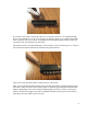
Before connecting the disk and memory expansion board to the computer, remove the shorting blocks
from the JP1 and JP2 jumpers on the main computer board. This picture shows them in the proper,
“off” configuration for use with the disk and memory expansion:
This disables the memory and input/output ports on the main computer board, so that the processor can
use the memory and ports on the disk and memory expansion board and serial interface board. You do
not need to physically remove the EPROM or RAM ICs from the main computer board. Also, there is
no need to place a starting address on the main board input port switches; the version 8 ROM code
jumps right into the monitor cold start address at startup, and these switches are disabled anyway.
Connect the disk and memory expansion board to the computer using the same ribbon connectors used
to connect the bus display board. Make sure the connectors are not misaligned:
10