
User Manual


Enterprise Self-Encrypting Drive User’s Guide, Rev. B 25
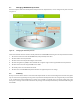
6.0 AES encryption algorithm
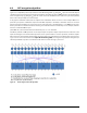
Figure 16 is a simplified pictorial representation of the AES128 algorithm. P
0
through P
15
represent a block of 16 bytes
(128 bits) of clear text message being input to the hardware. Each message byte is XOR’d with the corresponding byte
of the encryption key (K
0
through K
15
) and the results are fed to substitution boxes (which are just look-up tables)
where each 8-bit input maps to an 8-bit output.
It may appear somewhat random, but the outputs of the substitution boxes are fed to a series of 4-byte Mixers in a
particular cyclic pattern. Substitution output S
0
feeds Mixer input M
0
, S
1
feeds M
5
, S
2
feeds M
10
and so on. For those
purists interested in formulas, the connections can be represented as S
n
feeds M
y
where y = (5n MOD 16). The state-
ment in parentheses is shorthand notation meaning “the remainder when 5n is divided by 16.” For example, Substitu-
tion box 11 would feed Mixer input
(5x11 MOD 16) = (the remainder when 55 is divided by 16) = 7, so S
11
feeds M
7
.
The Mixers perform an XOR operation on the 4 input bytes and produce 4-byte outputs which are fed back to the
inputs P0 through P15 so that the whole operation can be repeated. After 10 or more repetitions, the mixer outputs
will be stored as encrypted data and the whole operation starts over again with the next 128 bits of the clear text mes-
sage. As can be seen in the discussion on Cipher Block Chaining (CBC), the encryption key input (K0 through K15) is
effectively modified every time a new 128-bit chunk of the clear text message is processed.
Figure 16. Block diagram of the AES algorithm