
User Manual


SCSI Commands Reference Manual, Rev. J 453
www.seagate.com Parameters for direct access devices
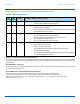
RECEIVER THRESHOLD CONTROL field
The Receiver Threshold Control field contains either the user input (MODE SELECT) or current (MODE SENSE) receiver threshold setting of the
target device SAS phy. If the user input setting is out of range of the transceiver capability, the target device shall return a CHECK CONDITION
status with the sense key set to ILLEGAL REQUEST and the additional sense code set to INVALID FIELD IN PARAMETER LIST for the MODE
SELECT command. The Receiver Threshold Control field shall be supported as described in
table 426. This field is changeable but not savable.
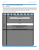
Table 426 Receiver Threshold Control
RECEIVER EQUALIZATION GAIN CONTROL field
The Receiver Equalization Gain Control field contains either the user input (MODE SELECT) or current (MODE SENSE) receiver equalization gain
setting of the target device SAS phy. If the user input setting is out of range of the transceiver capability, the target device shall return a CHECK
CONDITION status with the sense key set to ILLEGAL REQUEST and the additional sense code set to INVALID FIELD IN PARAMETER LIST for the
MODE SELECT command. This field shall be supported as described in
table 427. This field is changeable but not savable.
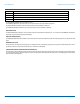
Table 427 Receiver Equalization Gain Control field
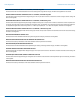
MANUFACTURER DEFINED BYTES FOR RECEIVER CONTROL field
The Manufacturer Defined Bytes For Receiver Control field may be used by manufacturer who needs additional control bytes for the receiver.
All control bytes shall accept 66h as reset code which change the control byte back to factory default setting. If the user input setting is out of
range of the transceiver capability, the target device shall return a CHECK CONDITION status with the sense key set to ILLEGAL REQUEST and
the additional sense code set to INVALID FIELD IN PARAMETER LIST for the MODE SELECT command.
EYE WIDTH MARGIN and EYE HEIGHT MARGIN field - Read Only
These fields shall contain IRE margin after IREC (Internal RX Eye Capture) is performed. The margin calculation are based on the following for-
mula:
Eye Width Margin = (Captured Eye Width - Spec Min Eye Width) / Spec Min Eye Width x 100%
Eye Height Margin = (Captured Eye Height - Spec Min Height Width) / Spec Min Eye Height x 100%
In case the Captured Eye is less than Spec Min. Eye, then FFh should be used.
IREC (INTERNAL RX EYE CAPTURE) bit
This bit controls the Internal RX Eye Capture process (see table 427), and provides the internal eye height, eye width and eye margin.
IREC COMPLETED bit - Read Only
This bit indicates the Internal RX Eye Capture process (see table 427) is completed and provides the internal eye height, eye width and eye mar-
gin.
Value Definition
0x66 (write only) Write 66h shall reset the receiver threshold setting back to factory default value.
0x00 – Range Limit
(write only)
User input for receiver threshold control setting. If the new user input is out of range specified in
subpage 19h/E5h, the target device shall maintain the current setting.
Read Only The current setting value shall be displayed.
Value Definition
0x66 (write only) Write 66h shall reset the receiver equalization gain setting back to factory default value for the driver
voltage.
0x00 – Range Limit
(write only)
User input for receiver equalization gain control setting. If the new user input is out of range
specified in subpage 19h/E5h, the target device shall maintain the current setting
Read Only The current setting value shall be displayed.