
User Manual


SCSI Commands Reference Manual, Rev. J 359
www.seagate.com Parameters for direct access devices
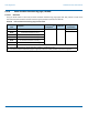
ATTACHED SSP INITIATOR PORT bit
1 An ATTACHED SSP INITIATOR PORT bit set to one indicates that an SSP initiator port is present in the attached device.
0 An ATTACHED SSP INITIATOR PORT bit set to zero indicates that an SSP initiator port is not present in the attached device.
ATTACHED STP INITIATOR PORT bit
1 An ATTACHED STP INITIATOR PORT bit set to one indicates that an STP initiator port is present in the attached device.
0 An ATTACHED STP INITIATOR PORT bit set to zero indicates that an STP initiator port is not present in the attached device.
ATTACHED SMP INITIATOR PORT bit
1 An ATTACHED SMP INITIATOR PORT bit set to one indicates that an SMP initiator port is present in the attached device.
0 An ATTACHED SMP INITIATOR PORT bit set to zero indicates that an SMP initiator port is not present in the attached device.
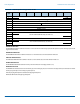
ATTACHED SSP TARGET PORT bit
1 An ATTACHED SSP TARGET PORT bit set to one indicates that an SSP target port is present in the attached device.
0 An ATTACHED SSP TARGET PORT bit set to zero indicates that an SSP target port is not present in the attached device.
ATTACHED STP TARGET PORT bit
1 An ATTACHED STP TARGET PORT bit set to one indicates that an STP target port is present in the attached device.
0 An ATTACHED STP TARGET PORT bit set to zero indicates that an STP target port is not present in the attached device.
ATTACHED SMP TARGET PORT bit
1 An ATTACHED SMP TARGET PORT bit set to one indicates that an SMP target port is present in the attached device.
0 An ATTACHED SMP TARGET PORT bit set to zero indicates that an SMP target port is not present in the attached device.
SAS ADDRESS field
The SAS ADDRESS field indicates the port identifier (see SPL-3 r02, Section 4.2.9) of the SAS port transmitting the IDENTIFY
address frame. For expander ports, the SAS ADDRESS field indicates the device name (see SPL-3 r02, Section 4.2.6) of the
expander device transmitting the IDENTIFY address frame.
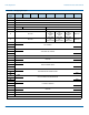
ATTACHED SAS ADDRESS field
The ATTACHED SAS ADDRESS field contains SAS address of the attached SAS port (see SPL-3 r02, Section 4.2.9).
ATTACHED PHY IDENTIFIER field
The ATTACHED PHY IDENTIFIER field contains the phy identifier of the attached SAS phy in the attached SAS device.
INVALID DWORD COUNT field
The INVALID DWORD COUNT field indicates the number of invalid dwords (see SPL-3 r02, Section 3.1.99) that have been received
outside of phy reset sequences (i.e., between when the SP state machine (see SPL-3 r02, Section 5.12) sends a Phy Layer Ready
(SAS) confirmation or Phy Layer Ready (SATA) confirmation and when it sends a Phy Layer Not Ready confirmation to the link
layer). The count shall stop at the maximum value. The INVALID DWORD COUNT field is set to a vendor-specific value after power
on.
For the INVALID DWORD COUNT field, RUNNING DISPARITY ERROR COUNT field, LOSS OF DWORD SYNCHRONIZATION COUNT
field, and PHY RESET PROBLEM COUNT field, the phy may maintain any size counter but should maintain a 32-bit counter. If it
reaches its maximum value, then the counter shall stop and the device server shall set the field to FFFFFFFFh in the SAS phy log
descriptor.
RUNNING DISPARITY ERROR COUNT field
The RUNNING DISPARITY ERROR COUNT field indicates the number of dwords containing running disparity errors (see SPL-3 r02,
Section 5.3.5) that have been received outside of phy reset sequences. The count shall stop at the maximum value. The RUNNING
DISPARITY ERROR COUNT field is set to a vendor-specific value after power on.