
User Manual


SCSI Commands Reference Manual, Rev. J 275
www.seagate.com Direct Access Block commands (SPC-5 and SBC-4)
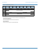
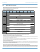
3.73 WRITE SAME (10) command
The WRITE SAME(10) command (see table 236) requests that the device server transfer a single logical block from the Data-Out
Buffer and for each LBA in the specified range of LBAs:
a) perform a write operation using the contents of that logical block; or
b) perform an unmap operation.
The device server writes (i.e., subsequent read operations behave as if the device server wrote the single block of user data
received from the Data-Out Buffer to each logical block without modification (see SBC-4).
If the medium is formatted with protection information and the WRPROTECT field is set to 000b, then the device server shall
write the LOGICAL BLOCK GUARD field, APPLICATION TAG field, and LOGICAL BLOCK REFERENCE TAG field (see4.22) for each
logical block as described in table119 (i.e., code equal to 000b row of table119).
If:
a) the medium is formatted with protection information;
b) the WRPROTECT field is not set to 000b or a reserved value (seetable119); and
c) the protection information from the Data-Out Buffer is set to FFFF_FFFF_FFFF_FFFFh,
then the device server shall write FFFF_FFFF_FFFF_FFFFh to the protection information for each logical block.
If:
a) the medium is formatted with type 1 or type 2 protection information;
b) the WRPROTECT field is not set to 000b or a reserved value (seetable119); and
c) the protection information from the Data-Out Buffer is not set to FFFF_FFFF_FFFF_FFFFh,
then:
a) the device server shall write the value from the LOGICAL BLOCK REFERENCE TAG field (see4.22) received in the logical block from the
Data-Out Buffer into the corresponding LOGICAL BLOCK REFERENCE TAG field of the first logical block written. The device sever shall
write the value of the previous LOGICAL BLOCK REFERENCE TAG field plus one into each of the subsequent LOGICAL BLOCK REFERENCE
TAG fields;
b) if the ATO bit is set to one in the Control mode page (see SPC-5) and the and the ATMPE bit is set to zero in the Control mode page, then
the device server shall write the logical block application tag received in the logical block from the Data-Out Buffer into the correspond-
ing LOGICAL BLOCK APPLICATION TAG field (see4.22) of each logical block;
c) if the ATO bit is set to one in the Control mode page and the and the ATMPE bit is set to zero in the Control mode page, then the device
server shall write the value defined in the Application Tag mode page (see6.5.3) into the corresponding LOGICAL BLOCK APPLICATION
TAG field of each logical block;
d) if the ATO bit is set to zero in the Control mode page, then the device server may write any value into the LOGICAL BLOCK APPLICATION
TAG field of each logical block; and
e) the device server shall write the value from the LOGICAL BLOCK GUARD field (see4.22) received in the logical block from the Data-Out
Buffer into the corresponding LOGICAL BLOCK GUARD field of each logical block.
If:
a) the medium is formatted with type 3 protection information;
b) the WRPROTECT field is not set to 000b or a reserved value (seetable119); and
c) the protection information from the Data-Out Buffer is not set to FFFF_FFFF_FFFF_FFFFh,
then:
a) if the ATO bit is set to one in the Control mode page (see SPC-5), then the device server shall write the value from the LOGICAL BLOCK
REFERENCE TAG field and the LOGICAL BLOCK APPLICATION TAG field received in the logical block from the Data-Out Buffer into the
corresponding LOGICAL BLOCK REFERENCE TAG field of each logical block;
b) if the ATO bit is set to zero in the Control mode page, then the device server may write any value into the LOGICAL BLOCK REFERENCE
TAG field of each logical block; and
c) the device server shall write the value from the LOGICAL BLOCK GUARD field and the LOGICAL BLOCK APPLICATION TAG field received
in the logical block from the Data-Out Buffer into the corresponding LOGICAL BLOCK GUARD field of each logical block.