
User Manual


SCSI Commands Reference Manual, Rev. J 267
www.seagate.com Direct Access Block commands (SPC-5 and SBC-4)
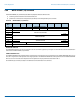
3.70.7 Download microcode with offsets and activate mode (06h)
In this mode, microcode shall be transferred to the device server using one or more WRITE BUFFER commands and activated (see
SPC-5).
The MODE SPECIFIC field is reserved.
The BUFFER ID field specifies a buffer within the logical unit. The vendor assigns buffer ID codes to buffers within the logical unit.
A buffer ID value of zero shall be supported. If more than one buffer is supported, then additional buffer ID codes shall be
assigned contiguously, beginning with one. If an unsupported buffer ID code is specified, the command shall be terminated with
CHECK CONDITION status, with the sense key set to ILLEGAL REQUEST, and the additional sense code set to INVALID FIELD IN
CDB.
The BUFFER OFFSET field specifies the location in the buffer to which the microcode is written. The application client shall send
commands that conform to the offset boundary requirements returned in the READ BUFFER descriptor (see table 106). If the
device server is unable to process the specified buffer offset, the command shall be terminated with CHECK CONDITION status,
with the sense key set to ILLEGAL REQUEST, and the additional sense code set to INVALID FIELD IN CDB.
The PARAMETER LIST LENGTH field specifies the maximum number of bytes that shall be present in the Data-Out Buffer to be
stored in the specified buffer beginning at the buffer offset. The application client should ensure that the parameter list length
plus the buffer offset does not exceed the capacity of the specified buffer. If the BUFFER OFFSET and PARAMETER LIST LENGTH
fields specify a transfer in excess of the buffer capacity, then the command shall be terminated with CHECK CONDITION status,
with the sense key set to ILLEGAL REQUEST, and the additional sense code set to INVALID FIELD IN CDB.
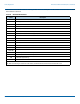
3.70.8 Download microcode with offsets and save mode (07h)
In this mode, microcode shall be transferred to the device server using one or more WRITE BUFFER commands, saved to
nonvolatile storage, and activated (see 5.4) based on the setting of the ACTIVATE MICROCODE field in the Extended INQUIRY VPD
page (see 5.4.9).
The BUFFER ID field, BUFFER OFFSET field, and PARAMETER LIST LENGTH field are defined in the download microcode with
offsets mode (see 3.70.7).
3.70.9 Write data to echo buffer mode (0Ah)
In this mode the device server transfers data from the application client and stores it in an echo buffer. An echo buffer is assigned
in the same manner by the device server as it would for a write operation. Data shall be sent aligned on four-byte boundaries.
The BUFFER ID and BUFFER OFFSET fields are ignored in this mode.
Upon successful completion of a WRITE BUFFER command the data shall be preserved in the echo buffer unless there is an
intervening command to any logical unit in which case the data may be changed.
The PARAMETER LIST LENGTH field specifies the maximum number of bytes that shall be transferred from the Data-Out Buffer to
be stored in the echo buffer. The application client should ensure that the parameter list length does not exceed the capacity of
the echo buffer. The capacity of the echo buffer is indicated by the BUFFER CAPACITY field in the READ BUFFER echo buffer
descriptor (see Table 108). If the PARAMETER LIST LENGTH field specifies a transfer in excess of the buffer capacity, the command
shall be terminated with CHECK CONDITION status, with the sense key set to ILLEGAL REQUEST, and the additional sense code
set to INVALID FIELD IN CDB.