
User Manual


SCSI Commands Reference Manual, Rev. J 248
www.seagate.com Direct Access Block commands (SPC-5 and SBC-4)
3.59 WRITE (6) command
This command has been declared obsolete by the T10 committee. However, it is included because it may be implemented on
some products.
The WRITE (6) command (see table 215) requests that the device server transfer the specified logical block(s) from the data-out
buffer and write them. Each logical block transferred includes user data but does not include protection information. Each
logical block written includes user data and, if the medium is formatted with protection information enabled, protection
information.
The cache control bits are not provided for this command. Direct-access block devices with cache may have values for the cache
control bits that may affect the WRITE (6) command, however no default value is defined by this manual. If explicit control is
required, the WRITE (10) command should be used.
LOGICAL BLOCK ADDRESS field
See 2.2.3 for the definition of the LOGICAL BLOCK ADDRESS field.
TRANSFER LENGTH field
The TRANSFER LENGTH field specifies the number of contiguous logical blocks of data that shall be transferred from the data-out buffer
and written, starting with the logical block specified by the LOGICAL BLOCK ADDRESS field. A TRANSFER LENGTH field set to zero spec
-
ifies that 256 logical blocks shall be written. Any other value specifies the number of logical blocks that shall be written. If the logical
block address plus the transfer length exceeds the capacity of the medium, the device server shall terminate the command with CHECK
CONDITION status with the sense key set to ILLEGAL REQUEST and the additional sense code set to LOGICAL BLOCK ADDRESS OUT OF
RANGE. The TRANSFER LENGTH field is constrained by the MAXIMUM TRANSFER LENGTH field in the Block Limits VPD page.
If a WRITE (6) command is received after protection information is enabled the device server shall set the protection information as
follows as it writes each logical block to the medium:
a) the LOGICAL BLOCK GUARD field set to a properly generated CRC (see SPC-5);
b) the LOGICAL BLOCK REFERENCE TAG field set to:
A) the least significant four bytes of the LBA, if type 1 protection (see SPC-5) is enabled; or
B) FFFFFFFFh, if type 2 protection or type 3 protection is enabled
and
a) the LOGICAL BLOCK APPLICATION TAG field set to:
C) FFFFh, if the ATO bit is set to one in the Control mode page (see 5.3.12); or
D) any value, if the ATO bit is set to zero in the Control mode page (see 5.3.12).
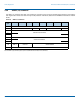
Table 215 WRITE (6) command
Bit
Byte
7 6 5 4 3 2 1 0
0 OPERATION CODE (0Ah)
1 Reserved (MSB)
2
LOGICAL BLOCK ADDRESS
3 (LSB)
4 TRANSFER LENGTH
5 CONTROL