002 Shop Manual Volume 2 GTX DI, GTX 4-TEC
Legal deposit: National Library of Quebec 2nd trimester 2002 National Library of Canada All rights reserved. No parts of this manual may be reproduced in any form without the prior written permission of Bombardier Inc. ©Bombardier Inc. 2002 Technical Publications Bombardier Inc. Valcourt (Quebec) Canada Printed in Canada ®*Registered trademarks of Bombardier Inc.
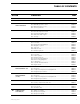
TABLE OF CONTENTS SECTION SUBSECTION PAGE SAFETY NOTICE .................................................................................................................................. III INTRODUCTION ................................................................................................................................... IV 01 SERVICE TOOLS AND PRODUCTS 01 - Table of contents ...................................................................... 02 - Mandatory service tools...........
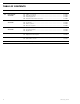
TABLE OF CONTENTS II 11 ELECTRICAL SYSTEM 01 - Table of contents ...................................................................... 02 - Charging system....................................................................... 03 - Starting system......................................................................... 04 - Instruments and accessories.................................................... 11-01-1 11-02-1 11-03-1 11-04-1 12 PROPULSION SYSTEM 01 - Table of contents .....................
SAFETY NOTICE SAFETY NOTICE 0 This manual has been prepared as a guide to correctly service and repair 2002 SEA-DOO watercraft. See model list below. This edition was primarily published to be used by watercraft mechanical technicians who are already familiar with all service procedures relating to Bombardier made watercraft. Mechanical technicians should attend training courses given by Bombardier Training Dept.
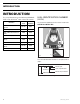
INTRODUCTION INTRODUCTION This Shop Manual covers the following BOMBARDIER made SEA-DOO® 2002 watercraft models. ENGINE TYPE MODEL NUMBER GTX DI International (green) 947 DI 5563 GTX DI (green) 947 DI 5564 GTX 4-TEC International (red) 1503 5573 GTX 4-TEC (red) 1503 5574 GTX 4-TEC International (blue) 1503 5593 GTX 4-TEC (blue) 1503 5594 GTX DI International (blue) 947 DI 5595 GTX DI (blue) 947 DI 5596 MODELS 0 HULL IDENTIFICATION NUMBER (H.I.N.
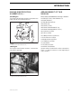
INTRODUCTION ENGINE IDENTIFICATION NUMBER (E.I.N.) ARRANGEMENT OF THIS MANUAL 947 DI Engine The Engine Identification Number is located on the upper side of the magneto housing.
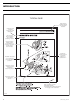
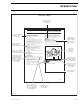
INTRODUCTION TYPICAL PAGE Page heading indicates section and subsection detailed. Subsection title indicates beginning of the subsection. Subsection 04 (MAGNETO SYSTEM) Italic sub-title above exploded view indicate pertaining models. Drop represents a liquid product to be applied to a surface. In this case Loctite 243 to screw threads. Loctite 243 Loctite 243 Dotted box contains parts of a particular model or an exploded view.
INTRODUCTION TYPICAL PAGE Sub-title with part name(s) from exploded view. Section 06 FUEL SYSTEM Subsection 03 (CARBURETORS) Title indicates main procedure to be carried-out. Service tool to be used to perform a certain procedure. Title in italic indicates a particular procedure concerning a model. Sub-sub-title in this case indicates that particular procedure for XP is finished, so from this point, all others models are concerned.
INTRODUCTION LIST OF ABBREVIATIONS USED IN THIS MANUAL DESCRIPTION OPS Oil Pressure Sensor OPT Optional OSPS Oil Separator Pressure Sensor AC Alternate Current P/N Part Number ADC Analog to Digital Conversion PFD Personal Flotation Device APS Air Pressure Sensor PSI Pound Per Square Inch ATS Air Temperature Sensor PTO Power Take Off B.U.D.S.
INTRODUCTION GENERAL INFORMATION The use of LEFT (port) and RIGHT (starboard) indications in the text, always refers to driving position (when sitting on watercraft). Besides, in the marine industry, FRONT is called BOW and REAR is called STERN. 1 2 As many of the procedures in this manual are interrelated, we suggest, that before undertaking any task, you read and thoroughly understand the entire section or subsection in which the procedure is contained.
INTRODUCTION EPA Emission Regulations All new 1999 and more recent Sea-Doo watercrafts manufactured by Bombardier are certified to the EPA as conforming to the requirements of the regulations for the control of air pollution from new watercraft engines. This certification is contingent on certain adjustments being set to factory standards. For this reason, the factory procedure for servicing the product must be strictly followed and, whenever practicable, returned to the original intent of the design.
INTRODUCTION Blind Holes 1. Clean threads (stud and hole) with solvent. 2. Apply Loctite Primer N (P/N 293 800 041) on threads and allow to dry. 3. Put several drops of proper strength Loctite threadlocker on female threads and in hole. 4. Apply several drops of proper strength Loctite on stud threads. 5. Install stud. 6. Install cover, etc. 7. Apply drops of proper strength Loctite on uncovered threads. 8. Tighten nuts as required. 1 2 A00A3MA Preassembled Parts 1. On threads 2.
INTRODUCTION Adjusting Screw Standard Thread Repair 1. Follow instructions on Loctite FORM-A-THREAD 81668 package. 2. If a plate is used to align bolt: a. Apply release agent on mating surfaces. b. Put waxed paper or similar film on the surfaces. 3. Twist bolt when inserting it to improve thread conformation. NOTE: NOT intended for engine stud repairs. 2 1 Repair of Small Holes/Fine Threads Option 1: Enlarge damaged hole, then follow Standard Thread Repair procedure.
INTRODUCTION NOTE: Avoid grinding. 2. Clean both mating surfaces with solvent. 3. Spray Loctite Primer N on both mating surfaces and on both sides of gasket. Allow to dry 1 or 2 minutes. 4. Apply GASKET ELIMINATOR 518 (P/N 293 800 038) on both sides of gasket, using a clean applicator. 5. Place gasket on mating surfaces and assemble immediately. NOTE: If the cover is bolted to blind holes (above), apply proper strength Loctite in the hole and on threads. Tighten.
INTRODUCTION TIGHTENING TORQUES N•m Tighten fasteners to torque mentioned in exploded views and text. When they are not specified refer to following table.The table also gives the metric conversion. N•m Lbf•in 1 2 3 4 5 6 7 8 9 10 11 12 13 14 15 16 17 18 19 M6 9 18 27 35 44 53 62 71 80 89 97 106 115 124 133 142 150 159 168 N•m FASTENER SIZE (8.8 grade) Lbf•ft 20 21 22 23 24 25 26 27 28 29 30 31 32 33 34 35 36 XIV FASTENER SIZE (8.
INTRODUCTION N•m FASTENER SIZE (8.8 grade) 81 82 83 84 85 86 87 88 89 90 91 92 93 94 95 96 97 98 99 100 101 102 103 104 105 106 107 108 109 110 111 112 113 114 115 Lbf•ft N•m 60 60 61 62 63 63 64 65 66 66 67 68 69 69 70 71 72 72 73 74 74 75 76 77 77 78 79 80 80 81 82 83 83 84 85 116 117 118 119 120 121 122 123 124 125 126 127 128 129 130 131 132 133 134 135 136 137 138 139 140 141 142 143 144 145 146 147 148 149 150 FASTENER SIZE (8.