
Memory Card Specification Sheet


©Copyright 2000-2007 SD Card Association
SDIO Simplified Specification Version 2.00
24
5.3 IO_RW_EXTENDED Command (CMD53)
In order to read and write multiple I/O registers with a single command, a new command, IO_RW_EXTENDED
is defined. This command is included in command class 9 (I/O Commands). This command allows the reading
or writing of a large number of I/O registers with a single command. Since this is a data transfer command, it
provides the highest possible transfer rate.
S D Command
Index
110101b
R/W
flag
Function
Number
Block
Mode
OP
Code
Register Address Byte/Block
Count
CRC
7
E
1 1 6 1 3 1 1 17 9 7 1
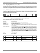
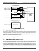
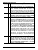
Figure 5-4 IO_RW_EXTENDED Command
The IO_RW_EXTENDED Command contains the following fields:
S(tart bit): Start bit. Always 0
D(irection): Direction. Always1 indicates transfer host to card.
Command Index: Identifies the “IO_RW_EXTENDED” command with a value of 110101b
R/W Flag: This bit determines the direction of the I/O operation. If this bit is 0, this command
reads data from the SDIO card at the address specified by the Function Number and
the Register Address to the host. The read data shall be returned on the DAT[x]
lines. If this bit is set to 1, the command shall write the bytes from the DAT[x] lines to
the I/O location addressed by the Function Number and the Register Address.
Function Number: The number of the function within the I/O card you wish to read or write. Note that
function 0x00 selects the common I/O area (CIA).
Block Mode (Optional) this bit, if set to 1, indicates that the read or write operation shall be
performed on a block basis, rather than the normal byte basis. If this bit is set, the
Byte/Block count value shall contain the number of blocks to be read/written. The
block size for functions 1-7 is set by writing the block size to the I/O block size
register in the FBR (See Table 6-3 and Table 6-4). The block size for function 0 is set
by writing to the FN0 Block Size register in the CCCR. Card and host support of the
block I/O mode is optional. The host can determine if a card supports block I/O by
reading the Card supports MBIO bit (SMB) in the CCCR (see Table 6-2). The block
size used when Block Mode = 1 and the maximum byte count per command used
when Block Mode = 0 can be read from the CIS in the tuple
TPLFE_MAX_BLK_SIZE (see 16.7.4) on a per-function basis.
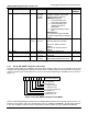
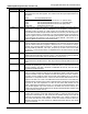
OP code Defines the read/write operation as described in Table 5-2
OP code Command operation
0 Multi byte R/W to fixed address
1 Multi byte R/W to incrementing address
Table 5-2 IO_RW_ EXTENDED command Op Code Definition
• OP Code 0 is used to read or write multiple bytes of data to/from a single I/O register
address. This command is useful when I/O data is transferred using a FIFO inside of
the I/O card. In this case, multiple bytes of data are transferred to/from a single
register address. For this operation, the address of the register is set into the
Register Address field. Data is transferred on the DAT[0] or DAT[3:0] lines as defined
for SD memory cards.
• OP Code 1 is used to read or write multiple bytes of data to/from an I/O register