
Memory Card Specification Sheet

©Copyright 2000-2007 SD Card Association
SDIO Simplified Specification Version 2.00
17
I/O Memory Control Method
Initialized Not
Initialized
CCCR
Not
Initialized
Initialized ACMD6
Initialized Initialized CCCR & ACMD6
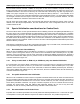
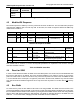
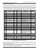
Table 4-4 Combo Card 4-bit Control
As shown in Table 4-4, if only the I/O function of a combo card is active, only writing to the CCCR is required
change the bus width mode. If only memory is active then ACMD6 is all that is needed to change bus widths. If
both I/O and Memory are active then both CCCR and ACMD6 are needed to change the bus width. In the
combo card, both the memory and I/O controllers shall be set to the same bus width
Note that Low-Speed SDIO cards support 4-bit transfer as an option. When communicating with a Low-Speed
SDIO card, the host shall first determine if the card supports 4-bit transfer prior to attempting to select that mode.
If a Combo card supports the lock/unlock operation, it cannot change bus width of a locked card and returns an
illegal command error to a bus width switch command. The host needs to unlock the card by CMD42 before
changing bus width. This also implies that the host should not change bus width during initialization before
managing a locked card.
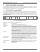
4.6 Card Detect Resistor
SD memory and I/O cards use a pull-up resistor on DAT[3] to detect card insertion. The procedure to
enable/disable this resistor is different between SD memory and SDIO. SD memory uses ACMD42 to control
this resistor while SDIO uses writes to the CCCR using CMD52. In the case of a combo card, both control
locations exist and shall be managed by the host. For a combo card, the resistor is enabled only when both
the
memory and the I/O control registers have the resistor enabled. That is, after a power on, the host shall disable
the resistor using ACMD42 to the memory controller or a CCCR write to the SDIO controller since the resistor
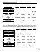
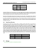
enable is a logical AND of the two enables. Table 4-5 shows the effect of each resistor enable on the card’s
resistor. After power-up, both locations default to resistor enabled. Note that after an I/O reset, the I/O resistor
enable is not changed. Note that the SDIO Specification Version 1.00 required that both the SDIO and Memory
resistor be disabled in order for the resistor to actually be disabled (logical OR of the 2 enables). Combo cards
built to that specification require the host to disable both enables. It is recommended the host disable both
enables of any combo card to avoid problems with the difference between 1.0 and current specification based
cards.
I/O Resistor Memory Resistor Card Resistor
Enabled Enabled Resistor Connected
Enabled Disabled Resistor Disconnected
Disabled Enabled Resistor Disconnected
Disabled Disabled Resistor Disconnected
Table 4-5 Card Detect Resistor States
4.7 Timings
This section is not included in the Simplified Specification.
Table 4-6 is blanked