SD Specifications Part E1 SDIO Simplified Specification Version 2.
©Copyright 2000-2007 SD Card Association SDIO Simplified Specification Version 2.00 Revision History Date April 3, 2006 February 8, 2007 Version 1.10 2.00 Changes compared to previous issue Simplified Version Initial Release (1) Added method to change bus speed (Normal Speed up to 25MHz and High Speed up to 50 MHz) (2) Operational Voltage Requirement is extended to 2.7-3.
©Copyright 2000-2007 SD Card Association SDIO Simplified Specification Version 2.00 Release of SD Simplified Specification The following conditions apply to the release of the SD simplified specification ("Simplified Specification") by the SD Card Association. The Simplified Specification is a subset of the complete SD Specification which is owned by the SD Card Association.
©Copyright 2000-2007 SD Card Association SDIO Simplified Specification Version 2.00 Conventions Used in This Document Naming Conventions Some terms are capitalized to distinguish their definition from their common English meaning. Words not capitalized have their common English meaning. Numbers and Number Bases Hexadecimal numbers are written with a lower case “h” suffix, e.g., FFFFh and 80h. Binary numbers are written with a lower case “b” suffix (e.g., 10b).
©Copyright 2000-2007 SD Card Association SDIO Simplified Specification Version 2.00 Table of Contents 1. General Description ................................................................................................................................. 1 1.1 SDIO Features .................................................................................................................................... 1 1.2 Primary Reference Document .....................................................................
©Copyright 2000-2007 SD Card Association SDIO Simplified Specification Version 2.00 5.3.2 Special Timing for CMD53 Multi-Block Read.............................................................................. 25 6. SDIO Card Internal Operation................................................................................................................ 26 6.1 Overview ...........................................................................................................................................
©Copyright 2000-2007 SD Card Association SDIO Simplified Specification Version 2.00 16.2 Basic Tuple Format and Tuple Chain Structure ................................................................................. 51 16.3 Byte Order Within Tuples .................................................................................................................. 51 16.4 Tuple Version ..............................................................................................................................
©Copyright 2000-2007 SD Card Association SDIO Simplified Specification Version 2.00 Table of Tables Table 3-1 OCR Values for CMD5..................................................................................................................... 10 Table 4-1 Unsupported SD Memory Commands ............................................................................................. 16 Table 4-2 R6 response to CMD3 .............................................................................................
©Copyright 2000-2007 SD Card Association SDIO Simplified Specification Version 2.00 Table of Figures Figure 2-1 Signal connection to two 4-bit SDIO cards ....................................................................................... 3 Figure 3-1 SDIO response to non-I/O aware initialization.................................................................................. 4 Figure 3-2 Card initialization flow in SD mode (SDIO aware host) .............................................................
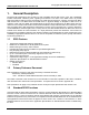
©Copyright 2000-2007 SD Card Association SDIO Simplified Specification Version 2.00 1. General Description The SDIO (SD Input/Output) card is based on and compatible with the SD memory card. This compatibility includes mechanical, electrical, power, signaling and software. The intent of the SDIO card is to provide high-speed data I/O with low power consumption for mobile electronic devices.
©Copyright 2000-2007 SD Card Association SDIO Simplified Specification Version 2.00 2. SDIO Signaling Definition 2.1 SDIO Card Types This specification defines two types of SDIO cards. The Full-Speed card supports SPI, 1-bit SD and the 4-bit SD transfer modes at the full clock range of 0-25MHz. The Full-Speed SDIO cards have a data transfer rate of over 100 Mb/second (10 MB/Sec). A second version of the SDIO card is the Low-Speed SDIO card. This card requires only the SPI and 1-bit SD transfer modes.
©Copyright 2000-2007 SD Card Association SDIO Simplified Specification Version 2.00 2.4 Signal Pins CLK CMD DAT[3:0] SD I/O Card SD Host CLK CMD DAT[3:0] SD I/O Card Figure 2-1 Signal connection to two 4-bit SDIO cards The rest of this chapter is not included in the Simplified Specification.
©Copyright 2000-2007 SD Card Association SDIO Simplified Specification Version 2.00 3. SDIO Card Initialization 3.1 Differences in I/O card Initialization A requirement for the SDIO specification is that an SDIO card shall not cause non-I/O aware hosts to fail when inserted. In order to prevent operation of I/O functions in non-I/O aware hosts, a change to the SD card identification mode flowchart is needed.
©Copyright 2000-2007 SD Card Association SDIO Simplified Specification Version 2.00 An SDIO aware host sends CMD5 prior to the CMD55/ACMD41 pair, and thus would receive a valid OCR in the R4 response to CMD5 and continue to initialize the card. Figure 3-2 shows the operation of an SDIO aware host operating in the SD modes and Figure 3-3 shows the same operation for a host that operates in the SPI mode.
©Copyright 2000-2007 SD Card Association SDIO Simplified Specification Version 2.00 Re-init Memory Power On Re-init IO MEM=0 IO=0, MEM=0 IO=0 CMD0 Pin1=High CMD52 IO Reset CMD8 is required to support High Capacity Memory.
©Copyright 2000-2007 SD Card Association SDIO Simplified Specification Version 2.
©Copyright 2000-2007 SD Card Association SDIO Simplified Specification Version 2.00 Re-init Memory Power On Re-init IO MEM=0 IO=0, MEM=0 IO=0 CMD0 CS=Low CMD52 IO Reset CMD8 is required to support High Capacity Memory.
©Copyright 2000-2007 SD Card Association SDIO Simplified Specification Version 2.00 C D Skip memory initialize or MEM=1 Test MEM Flag Execute memory initialize & MEM=0 Get memory OCR CMD58 Illegal Command OCR invalid Check Response OCR valid Set New Voltage (if needed) High Capacity Support Host: HCS=1 ACMD41 Arg=HCS, WV IDLE=1 1sec Timeout Check Response IDLE=0 Illegal Command MEM=1 Memory Initialized CMD58 If F8=1, CMD58 is required to get CCS. If F8=0, CSS=0.
©Copyright 2000-2007 SD Card Association SDIO Simplified Specification Version 2.00 3.2 The IO_SEND_OP_COND Command (CMD5) Figure 3-4 shows the format of the IO_SEND_OP_COND command (CMD5). The function of CMD5 for SDIO cards is similar to the operation of ACMD41 for SD memory cards. It is used to inquire about the voltage range needed by the I/O card. The normal response to CMD5 is R4 in either SD or SPI format.
©Copyright 2000-2007 SD Card Association SDIO Simplified Specification Version 2.00 3.3 The IO_SEND_OP_COND Response (R4) An SDIO card receiving CMD5 shall respond with a SDIO unique response, R4.
©Copyright 2000-2007 SD Card Association SDIO Simplified Specification Version 2.00 Once an SDIO card has received a CMD5, the I/O portion of that card is enabled to respond normally to all further commands. This I/O enable of the functions within the I/O card shall remain set until a reset, power cycle or CMD52 with write to I/O reset is received by the card. Note that a SD memory only card may respond to a CMD5.
©Copyright 2000-2007 SD Card Association SDIO Simplified Specification Version 2.
©Copyright 2000-2007 SD Card Association SDIO Simplified Specification Version 2.00 Figure 3-9 shows the equivalent command flow to re-initialize the memory controller of a Combo card. The RCA value of xxxxh denotes an RCA value of either 0x0000 or the prior RCA value. For new controller designs, a reset value of 0x0000 is recommended.
©Copyright 2000-2007 SD Card Association SDIO Simplified Specification Version 2.00 4. Differences with SD Memory Specification 4.1 SDIO Command List Table A-14 shows the list of commands accepted by SD memory and SDIO cards when using the SD bus interface. Table A-15 shows the list of commands accepted by SD memory and SDIO cards when using the SPI bus interface. 4.
©Copyright 2000-2007 SD Card Association SDIO Simplified Specification Version 2.00 SD Memory Command CMD18, CMD24, CMD25 SDIO Command Comment read/write commands. Table 4-1 Unsupported SD Memory Commands 4.3 Modified R6 Response The normal response to CMD3 by a memory card is R6 as shown in Table 4-2. The card status bits (23-8) are changed when CMD3 is sent to an I/O only card.
©Copyright 2000-2007 SD Card Association SDIO Simplified Specification Version 2.00 I/O Initialized Not Initialized Initialized Memory Not Initialized Initialized Control Method CCCR Initialized CCCR & ACMD6 ACMD6 Table 4-4 Combo Card 4-bit Control As shown in Table 4-4, if only the I/O function of a combo card is active, only writing to the CCCR is required change the bus width mode. If only memory is active then ACMD6 is all that is needed to change bus widths.
©Copyright 2000-2007 SD Card Association SDIO Simplified Specification Version 2.00 4.8 Data Transfer Block Sizes SDIO cards may transfer data in either a multi-byte (1 to 512 bytes) or an optional block format, while the SD memory cards are fixed in the block transfer mode. The SD Physical Specification limits the block size for data transfer to powers of 2 (i.e. 512, 1024, 2048) unless using partial read and write.
©Copyright 2000-2007 SD Card Association SDIO Simplified Specification Version 2.00 4.10.1 OCR Register All SD cards (memory, I/O and combo) shall have at least one OCR register. If the card is a combo card, it may have two OCR’s (one for memory and one for I/O). The memory portion of a combo card has an OCR accessed using ACMD41 and CMD58. The I/O portion of a card has an OCR with the same structure that is accessed via CMD5. If there are multiple OCR’s the voltage range may not be identical.
©Copyright 2000-2007 SD Card Association SDIO Simplified Specification Version 2.00 identify it as an I/O only response. I/O specific status is reported by I/O response and Memory specific status is reported by Memory response except for the following case: In the SD bus mode, the card shall not respond to an Illegal Command or a command with a CRC error. The indication of those two error cases shall be given by the card in the following command’s response.
©Copyright 2000-2007 SD Card Association SDIO Simplified Specification Version 2.00 5. New I/O Read/Write Commands Two additional data transfer instructions have been added to support I/O. IO_RW_DIRECT, a direct I/O command similar to the MMC 'Fast I/O' command, and IO_RW_EXTENDED, which allows fast access with byte or block addresses. Both commands are in class 9 (I/O Commands). 5.
©Copyright 2000-2007 SD Card Association SDIO Simplified Specification Version 2.00 5.2 IO_RW_DIRECT Response (R5) The SDIO card’s response to CMD52 shall be in one of two formats. If the communication between the card and host is in the 1-bit or 4-bit SD mode, the response shall be in a 48-bit response (R5) as described in 5.2.1. If the communication is using the SPI mode, the response shall be a 16-bit R5 response as described in 5.2.2. 5.2.
©Copyright 2000-2007 SD Card Association SDIO Simplified Specification Version 2.00 Bits Identifier Type 5-4 IO_CURRENT_STATE S 00=DIS 01=CMD 02=TRN 03=RFU 3 ERROR ER ERX ’0’= no error ’1’= error DIS=Disabled: Initialize, Standby and Inactive States (card not selected) CMD=DAT lines free: 1. Command waiting (No transaction suspended) 2. Command waiting (All CMD53 transactions suspended) 3.
©Copyright 2000-2007 SD Card Association SDIO Simplified Specification Version 2.00 5.3 IO_RW_EXTENDED Command (CMD53) In order to read and write multiple I/O registers with a single command, a new command, IO_RW_EXTENDED is defined. This command is included in command class 9 (I/O Commands). This command allows the reading or writing of a large number of I/O registers with a single command. Since this is a data transfer command, it provides the highest possible transfer rate.
©Copyright 2000-2007 SD Card Association SDIO Simplified Specification Version 2.00 address that increment by 1 after each operation. This command is used when large amounts of I/O data exist within the I/O card in a RAM like data buffer. In this operation, the start address is loaded into the Register Address field. The first operation occurs at that address within the I/O card. The next operation shall occur at address+1 with the address incrementing by 1 until the operation has completed.
©Copyright 2000-2007 SD Card Association SDIO Simplified Specification Version 2.00 6. SDIO Card Internal Operation I/O access differs from memory in that the registers can be written and read individually and directly without a FAT file structure or the concept of blocks (although block access is supported). These registers allow access to the I/O data, control of the I/O function and report on status or transfer I/O data to/from the host.
©Copyright 2000-2007 SD Card Association SDIO Simplified Specification Version 2.00 6.4 Suspend/Resume Within a multi-function SDIO or a Combo card, there are multiple devices (I/O and memory) that share access to the SD bus. In order to allow the sharing of access to the host among multiple devices, SDIO and combo cards can implement the optional concept of suspend/resume.
©Copyright 2000-2007 SD Card Association SDIO Simplified Specification Version 2.
©Copyright 2000-2007 SD Card Association SDIO Simplified Specification Version 2.
©Copyright 2000-2007 SD Card Association SDIO Simplified Specification Version 2.00 Field SDx Type Description R/O SD Format Version number. These 4 bits contain the version of the SD Physical Specification that this card supports. The codes for the SD Physical Specification are as follows: IOEx R/W IORx R/O IENx R/W IENM R/W INTx R/O ASx W/O RES W/O Value SD Physical Specification 0x00 SD Physical Specification Version 1.01 (March 2000) 0x01 SD Physical Specification Version 1.
©Copyright 2000-2007 SD Card Association SDIO Simplified Specification Version 2.00 Field Type Description Bus Width 1:0 R/W CD Disable R/W SCSI R/O ECSI R/W SDC R/O SMB R/O SRW R/O SBS R/O S4MI R/O Defines the data bus width (’00’=1-bit or’10’=4-bit bus) to be used for data transfer. All Full-Speed SDIO cards support both 1 and 4-bit bus. A Low-Speed SDIO card’s support of 4-bit bus is optional. On reset or power-on these bits are cleared to 00.
©Copyright 2000-2007 SD Card Association SDIO Simplified Specification Version 2.00 Field Type Description E4MI R/W LSC R/O 4BLS R/O Pointer to card’s common CIS R/O BS R/O BR R/W Enable interrupt between blocks of data in 4-bit SD mode. Enable the multi-block IRQ during 4-bit transfer for the SDIO card. When this bit is 0, the card shall not signal interrupts during a 4-bit multi-block data transfer.
©Copyright 2000-2007 SD Card Association SDIO Simplified Specification Version 2.00 Field Type Description FSx R/W Select Function bits 3:0 These four bits are used to select a function number (0-7) or the memory of a combo card (8) for Suspend/Resume. There are 2 means to write the value of FSx. First, an I/O writes to the register in the CCCR and second, a new I/O command causes the FSx to be set to the function number in that command. The value of FSx shall remain until overwritten.
©Copyright 2000-2007 SD Card Association SDIO Simplified Specification Version 2.00 Field Type Description SMPC R/O EMPC R/W SHS R/O EHS R/W RFU R/O Reserved for Vendors R/W Support Master Power Control These bits tell the host if the card supports Master Power Control. SMPC=0 : The total card current is less than 200mA, even if all functions are active (IOEx=1). EMPC,SPS and EPS shall be zero. SMPC=1 :The total card current may exceed 200mA. EMPC, SPS and EPS are available.
©Copyright 2000-2007 SD Card Association SDIO Simplified Specification Version 2.00 6.10 Function Basic Registers (FBR) In addition to the CCCR, each supported I/O function has a 256-byte area used to allow the host to quickly determine the abilities and requirements of each function, enable power selection for each function and to enable software loading. The address of this area is from 0x00n00 to 0x00nFF where n is the function number (0x1 to 0x7).
©Copyright 2000-2007 SD Card Association SDIO Simplified Specification Version 2.00 Field Function CSA Enable Type R/W Extended SDIO Standard Function interface code SPS (Support Power Selection) EPS (Enable Power Selection) R/O Description This bit controls access to the Code Storage Area for this function. If this bit is cleared to 0, then any read or write access to the CSA shall be blocked. If this bit is set to 1, then access to the CSA is allowed. This bit is cleared to 0 upon reset.
©Copyright 2000-2007 SD Card Association SDIO Simplified Specification Version 2.00 6.11 Card Information Structure (CIS) The Card Information Structure provides more complete information about the card and the individual functions. The CIS is the common area to read information about all I/O functions that exist in a card. The design is based on the PC Card16 design standardized by PCMCIA. All cards that support I/O shall have a common CIS and a CIS for each function.
©Copyright 2000-2007 SD Card Association SDIO Simplified Specification Version 2.00 6.14 Bus State Diagram Figure 6-2 shows the Bus State Diagram for an SDIO card. It shows the bus states and their relations to SDIO commands and Suspend/Resume.
©Copyright 2000-2007 SD Card Association SDIO Simplified Specification Version 2.00 7. Embedded I/O Code Storage Area (CSA) In order to support the concept of “Plug-and-Play” for SDIO cards, each function contained in a card may need to contain a block of memory for the storage of drivers and/or applications. In addition, since the same SDIO card may be used on multiple different host platforms, several different versions of the code may be needed for each function.
©Copyright 2000-2007 SD Card Association SDIO Simplified Specification Version 2.00 8. SDIO Interrupts In order to allow the SDIO card to interrupt the host, an interrupt function is added to a pin on the SD interface. Pin number 8, which is used as DAT[1] when operating in the 4-bit SD mode, is used to signal the card’s interrupt to the host. The use of interrupt is optional for each card or function within a card.
©Copyright 2000-2007 SD Card Association SDIO Simplified Specification Version 2.00 8.1.7 Terminated Data Transfer Interrupt Cycle This section is not included in the Simplified Specification. 8.1.8 Interrupt Clear Timing Since the SDIO card uses level sensitive interrupts, the host shall clear pending interrupts with an I/O read or write to some function unique area.
©Copyright 2000-2007 SD Card Association SDIO Simplified Specification Version 2.00 9. SDIO Suspend/Resume Operation The procedure used to perform the Suspend/Resume operation on the SD bus is: 1. The host determines which function is currently using the DAT[3:0] line(s). 2. The host requests the lower priority or slower transaction to suspend. 3. The host checks for the transaction suspension to complete. 4. The host begins the higher priority transaction. 5.
©Copyright 2000-2007 SD Card Association SDIO Simplified Specification Version 2.00 10. SDIO Read Wait Operation The optional Read Wait (RW) operation is defined only for the SD 1-bit and 4-bit modes. The read Wait operation allows a host to signal a card that is executing a read multiple (CMD53) operation to temporarily stall the data transfer while allowing the host to send commands to any function within the SDIO card.
©Copyright 2000-2007 SD Card Association SDIO Simplified Specification Version 2.00 11. Power Control 11.1 Power Control Overview The concept of high-power SDIO cards was introduced in Version 1.10 of the SDIO Specification. Power Control supports following two features: • High-Power Support SDIO cards created prior to Version 1.10 of the SDIO Specification were limited to a maximum current of 200mA at any time, irrespective of the number or types of functions supported.
©Copyright 2000-2007 SD Card Association SDIO Simplified Specification Version 2.00 11.2.2 Power Selection Power Selection defines two power modes for a function: Lower Current Mode and Higher Current Mode. A card implementing Power Selection gives the host the choice between these two power modes. These modes can be used for functions, such as a radio, which can operate in full performance (Higher Current Mode) or reduced performance (Lower Current Mode).
©Copyright 2000-2007 SD Card Association SDIO Simplified Specification Version 2.00 • 11.3.2 The host shall have the ability to manage power by calculating maximum current shown in the tuples and control EMPC, EPS and IOEx not to exceed total current that the host can supply. If the host does not have enough power to use the card, the host shall not enable the card. Power Control Operation A host reads the SMPC to see if the card supports Power Control additions.
©Copyright 2000-2007 SD Card Association SDIO Simplified Specification Version 2.00 12. High-Speed Mode High-Speed mode increases the bus clock rate to 50MHz and the SD bus throughput from 12.5MB/sec to 25MB/sec. For information on High-Speed mode for SD memory cards see Part 1 Physical Layer Specification Version 2.00, sections 4.3.10, 4.3.11 and 6.8. SDIO and combo cards may also support High-Speed mode. 12.1 SDIO High-Speed Mode SDIO version 1.
©Copyright 2000-2007 SD Card Association SDIO Simplified Specification Version 2.00 13. SDIO Physical Properties This chapter is not included in the Simplified Specification. 13.1 SDIO Form Factors The SDIO definition encompasses different form factors: • Full-Size SDIO — compatible with host sockets designed for SD memory cards • miniSDIO — compatible with host sockets designed for miniSD memory cards 13.2 Full-Size SDIO The SDIO card is compatible with host sockets designed for SD memory cards.
©Copyright 2000-2007 SD Card Association SDIO Simplified Specification Version 2.00 itself as drawing more power that the host is willing to supply, thus lower power cards may have a competitive advantage in the market. The rest of this chapter is not included in the Simplified Specification.
©Copyright 2000-2007 SD Card Association SDIO Simplified Specification Version 2.00 15. Inrush Current Limiting This chapter is not included in the Simplified Specification.
©Copyright 2000-2007 SD Card Association SDIO Simplified Specification Version 2.00 16. CIS Formats 16.1 CIS Reference Document The CIS used by SDIO is based directly upon the metaformat specification used by PCMCIA and Compact Flash.
©Copyright 2000-2007 SD Card Association SDIO Simplified Specification Version 2.00 16.4 Tuple Version With the introduction of SDIO Specification Version 1.10, a different format for the tuple information is possible based on the changes made by each specification revision. These changes could be added fields in a tuple or entirely new tuples. In order to maintain backward compatibility, new data fields are added after existing fields in order to maximize backward compatibility.
©Copyright 2000-2007 SD Card Association SDIO Simplified Specification Version 2.00 Note 1: the use of CISTPL_SDIO_STD is mandatory for all functions that claim to support a SDIO standard interface specification (see 1.3). If the function does not support a standard SDIO interface, this tuple should be used with a value of 0. 16.6 CISTPL_MANFID: Manufacturer Identification String Tuple The manufacturer identification tuple contains information about the manufacturer of a SDIO Card.
©Copyright 2000-2007 SD Card Association SDIO Simplified Specification Version 2.00 16.7.2 CISTPL_FUNCE: Function Extension Tuple The CISTPL_FUNCE tuple provides standard information about the card (common) and each individual function. There shall be one CISTPL_FUNCE in each function’s CIS immediately following the CISTPL_FUNCID tuple. The format of the CISTPL_FUNCE is shown in Table 16-5.
©Copyright 2000-2007 SD Card Association SDIO Simplified Specification Version 2.00 16.7.4 CISTPL_FUNCE Tuple for Function 1-7 This version of the CISTPL_FUNCE tuple gives the host common information about each individual function on a per-function basis. There shall be one of these tuples, located in the CIS for each function following the CISTPL_FUNCID. The format of this tuple is shown in Table 16-8.
©Copyright 2000-2007 SD Card Association SDIO Simplified Specification Version 2.00 TPLFE_CSA_SIZE TPLFE_CSA_PROPERTY TPLFE_MAX_BLK_SIZE TPLFE_OCR TPLFE_OP_MIN_PWR TPLFE_OP_AVG_PWR TPLFE_OP_MAX_PWR TPLFE_SB_MIN_PWR TPLFE_SB_AVG_PWR TPLFE_SB_MAX_PWR TPLFE_MIN_BW TPLFE_OPT_BW TPLFE_ENABLE TIMEOUT_VAL Size of the CSA space available for this function in bytes This byte contains flags identifying properties of this function’s CSA.
©Copyright 2000-2007 SD Card Association SDIO Simplified Specification Version 2.00 TPLFE_SP_AVG_PWR_3.3V TPLFE_SP_MAX_PWR_3.3V TPLFE_HP_AVG_PWR_3.3V TPLFE_HP_MAX_PWR_3.3V TPLFE_LP_AVG_PWR_3.3V TPLFE_LP_MAX_PWR_3.3V seconds. If the cards required no time-out, this field shall be set to 0x0000. This value is the same as that of TPLFE_OP_AVG_PWR. This value is the same as that of TPLFE_OP_MAX_PWR.
©Copyright 2000-2007 SD Card Association SDIO Simplified Specification Version 2.00 16.7.5 CISTPL_SDIO_STD: Function is a Standard SDIO Function This tuple code (0x91) has been reserved for use by SDIO devices that conform to the application specifications for standard SDIO functions, as defined in those separate specifications. The exact format for this tuple can be found in those specifications.
©Copyright 2000-2007 SD Card Association SDIO Simplified Specification Version 2.00 Appendix A (Normative) A.1 SD and SPI Command List Table A-14 and Table A-15 show the commands that are supported by SD memory and SDIO devices in both SPI and SD modes. If a command is not identified as either mandatory or optional, then it is not supported by that device.
©Copyright 2000-2007 SD Card Association SDIO Simplified Specification Version 2.
©Copyright 2000-2007 SD Card Association SDIO Simplified Specification Version 2.00 Appendix B (Normative) B.1 Normative References The following documents are referenced by this specification. This specification can apply to any released versions of below SD Specifications after Version 2.00. 1) SD Specifications Part 1 PHYSICAL LAYER SPECIFICATION Version 2.00 May 9, 2006 2) SD Specifications Part 1 miniSD Card Addendum Version 2.
©Copyright 2000-2007 SD Card Association SDIO Simplified Specification Version 2.00 Appendix C C.
©Copyright 2000-2007 SD Card Association SDIO Simplified Specification Version 2.00 LOW, HIGH MBIO miniSDIO Card MMC MSB, LSB OCR PCMCIA PnP R/O R/W RAW RCA Resume RFU ROM RWC SCR SDA SDCLK SDIO SDIO aware SPI Standard-Power SDIO Stuff bit(s) Binary interface states with defined assignment to a voltage level Multi-Block I/O A SDIO card based on the miniSD card form factor.
©Copyright 2000-2007 SD Card Association SDIO Simplified Specification Version 2.00 Appendix D (Informative) Appendix D is not included in the Simplified Specification.