PRECISION PRO 5500 VEHICLE SECURITY SYSTEM WITH REMOTE START PRECISION PRO 2200 REMOTE START ONLY PRODUCT MANUAL
Limited Lifetime Warranty This system is warranted to the original purchaser, to be free from defects in material and workmanship. The manufacturer will repair or replace at its option, and free of charge for the first twelve (12) months, any part that proves defective in material or workmanship under normal installation, use, and service, provided the product is returned to the manufacturer freight prepaid. After the first 12 month warranty period there will be a maximum service charge of $25.
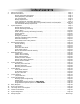
Table of Contents 1. 2. 3. 4. 5. 6. 7. 8. 9. 10. 11. 12. 13. 14. 15. About Your System . . . . . . . . . . . . . . . . . . . . . . . . . . . . . . . . . . . . . . . . . . . . . . . . . . . . . . .Page 1 Remote Transmitters . . . . . . . . . . . . . . . . . . . . . . . . . . . . . . . . . . . . . . . . . . . . . . . . . . . . . .Page 2 Remote Transmitter Description . . . . . . . . . . . . . . . . . . . . . . . . . . . . . . . . . . . . . . . . . .Page 3 Adding/Replacing Transmitters . . . . . . . .
About Your System The ScyTek Precision 5500 Series is a Combination Vehicle Security and Remote Starting System that will have features and functions that will be described in the following sections with an ASTERICK * The Precision 2200 Series is a Remote Start System only. Both series feature a built-in "ScyNet Network Port" that allows direct connection of optional accessory modules and a PC interface offering expanded system operation.
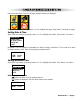
2-W WAY COLOR LCD REMOTE TRANSMITTER DESCRIPTION time date/engine run timer 11/16 3:10P Button 3 Button 4 Button 1 Button 5 Button 2 Battery status wakeup alarm enabled autostart enabled The 2-way Color remote transmitter is offering increased range and confirmation of any activated feature. Page 1 Button 1 Arms and Locks* the system and when held for 3 seconds, activates the system’s Panic feature. Button 1 also locks the doors when the system is in Valet Mode.
PAGER PARAMETERS SETTING Press and hold Buttons 2 and 3 until pager program features are displayed. Select pager setting by pressing buttons 1 or 2 to highlight the pager. Press button 3 to select the pager. Setting Date & Time Select Time Date setting by pressing buttons 1 or 2 to highlight the feature. Press button 3 to select it.
Use buttons 1 & 2 to highlight the time parameter you wish to change, use buttons 3 & 4 to scroll up or down to chage the time. Save the changes by pressing button 5. START SET AUTO ST ON TIME: 08:00A Setting Alarm Clock Select Alarm setting by pressing buttons 1 or 2 to highlight the feature. Press button 3 to select it. TIME DATE START TIME ALARM CLOCK SOUND ON BACK Enable/Disable Alarm Select Alarm Clock on/off by pressing button 3.
Return to Previous Screen Select Previous Screen by pressing buttons 1 or 2 to highlight the feature. Press button 3 to select it. TIME DATE START TIME ALARM CLOCK SOUND ON BACK Set System Parameters Press and hold Buttons 2 and 3 until pager program features are displayed. Select system setting by pressing buttons 1 or 2 to highlight the pager. Press button 3 to select the system features. Siren Chirp Enable/Disable Select Siren Chirp setting by pressing buttons 1 or 2 to highlight the feature.
Setting AutoStart Cold Temperature Threshold Select Cold Temp start setting by pressing buttons 1 or 2 to highlight the feature. Press button 3 to select it. SIREN CHIRP PASSIVE ARM COLD TEMP HOT TEMP BACK Use buttons 3 & 4 to scroll up or down to chage the temperature threshold. Save the changes by pressing button 5. AUTOSTART SET COLD TEMP TEMP: - 11oF Security system responce Setting AutoStart Hot Temperature Threshold Select Cold Temp Time setting by pressing buttons 1 or 2 to highlight the feature.
Synchronize System and Pager Clocks Select Clock Sync setting by pressing buttons 1 or 2 to highlight the pager. Press button 3 to select the pager. Pager Clock Sync This feature synchronizes the pager clock to the security system time of a day clock. Select Pager Clock Sync by pressing buttons 1 or 2 to highlight the feature. Press button 3 to select it.
START 1 SET SET TIME TIME: 8:00A Use buttons 1 & 2 to highlight Set Time press button 3. AUTOSTART 1 TIME: 8:00A The security system responce. Start Time 2 This feature sets the system Autostart 2 time. Select Sytem Clock Sync by pressing buttons 1 or 2 to highlight the feature. Press button 3 to select it. PGR CLK SYNC SYS CLK SYNC START 1 TIME START 2 TIME EXIT Use buttons 1 & 2 to highlight hours or minutes, use buttons 3 & 4 to scroll up or down to chage the time.
Programmable Functions using the Color Remote Pressing and holding transmitter button 5 will scroll through several transmitter programmable options - TEMPERATURE, ENABLE COLD START, ENABLE HOT START, VALET MODE, ENABLE AUTOSTART 1, ENABLE AUTOSTART 2. TEMPERATURE Check the temperature inside the vehicle 1. Press and hold Button 5 until the display shows TEMPERATURE 2. Release Button 5. · The transmitter will beep four times. ENABLE COLD START Auto Start Cold Temperature Activation Mode. 1.
Transmitter Lockout ADDITIONAL FUNCTION Press and hold buttons 2 & 4 simultanously for 3 seconds to lockout the transmitter against accidental transmission. Release Transmitter Lockout Press and hold buttons 2 & 4 simultanously for 3 seconds to release the transmitter from Lockout. Out of Range Report pager report if no responce from the unit.
Pager Status Display Time: time of day clock Date/Engine Run Timer: date, or engine run minute timer if remote start activated (20 min max). Battery Status: displays remaining battery life.
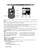
Remote Transmitters Standard Remote Transmitter Description LED Button 1 Button 2 Button 3 Button 4 Button 5 The Precision 5500, 2200 Series is supplied with one 5-button Remote Transmitter that is used to control the system’s operations. Note: Using the optional PC or Pocket PC interface with the network software, it is possible to reconfigure the functionality of the transmitter buttons. The standard (default) setting for operation of the transmitters is described below.
Adding/Replacing Standard Remote Transmitters To replace lost or stolen transmitters or to add additional transmitters into the system, have all desired transmitters ready and follow the steps below. Note: Up to 4 one-way transmitters can be programmed to operate the system. Any previously stored transmitter will be erased if it is not programed within the following sequence To program the transmitter(s): 1. Turn the ignition key On, Off, On, Off, and back On.
2-way LCD Remote Transmitter Description Button 1 Button 2 Button 3 Button 4 Button 5 The Precision 5500 and 2200 are supplied with a 2-way LCD remote transmitter, offering increased range and confirmation of any activated features. Page 1 Button 1 Arms* and Locks the system and when held for 5 seconds, activates the system’s Panic feature. Button 1 also locks the doors when the system is in Valet Mode. Button 2 Disarms* and Unlocks the system.
3. Press and release Button 1 on the first transmitter, then on the second transmitter. · The siren*/horn will chirp/honk once for every transmitter learned. 4. Turn off the ignition key. 5. The siren*/horn will chirp/honk 3 times to indicate the system has exited programming mode. LCD Transmitter Battery Replacement Your Precision Remote Transmitter uses a 1.5 volt AAA alkaline battery, which will require replacement in time.
To set the daily start feature: 1. Press and hold Buttons 2 and 3 until the remote beeps four times. · The fan and clock will be shown indicating daily start mode is entered. 2. Press Button 2 until the desired hour is displayed. 3. Press Button 3 until the desired minute is displayed. The button may be held down to scroll faster. 4. When the desired time is displayed, press Button 5 to store. · The remote will beep 3 times to indicate the daily start function has been set.
CHP Set the siren*/horn confirmation chirps*/honks ON or OFF: 1. Press and hold Button 5 until the display shows CHP. ·The transmitter will beep three times. 2. Release Button 5. · The transmitter will beep once. · The LCD panel will show a siren if the chirps*/honks are enabled or "off" if the chirps*/honks are disabled. snd sound function selects the transmitter's confirmation mode - Tone or Vibration mode. Set the transmitter confirmation tones ON or OFF: 1.
2. Release Button 5. · The transmitter will beep once. · The LCD panel will show Auto Start Hot Temperature setting. 3. Press and hold Button 5 until the display shows CON. 4. Release Button 5. · The transmitter will beep once.
System Operation Remote Arming*/Locking The system monitors 5 independent areas (zones) while armed: doors, hood/ trunk, shock sensor, optional sensor input, and the network port for future expansion.* To Arm* and Lock the System: 1. Turn off the ignition. 2. Press Button 1. · The siren*/horn will chirp/honk once. · The doors will lock.( if the keyless entry feature was installed) · The parking lights will flash once. · The LED will turn ON, to indicate the starter defeat is activated.* 3.
* Tamper Alert If the system was triggered while away, the LED will flash to indicate which zone triggered the system after disarming and turning on the ignition. The LED indication will repeat 5 times.
Panic Mode In the event of an emergency, the transmitter’s remote Panic feature can be used to instantly trigger the alarm*/panic feature. To activate the Panic Mode: 1. Press and hold Button 1 for 5 seconds. · The alarm will sound. · The parking lights will flash. · The doors will unlock** allowing access to the vehicle. 2. Press Button 1 or 2 to stop Panic Mode. * If the ignition is on when the Panic feature is activated, the doors will lock for personal safety.
To Emergency Override the system using the Code: 1. Follow steps 1-3 above. 2. Press the override switch a number of times equal to the Disarm code chosen, and continue holding for 10 seconds on the last press. · The system will disarm. If the code is entered incorrectly, turn off the ignition and begin again. To set the Emergency Override Code: 1. Turn on ignition. 2. Within 5 seconds, press the valet switch 5 times. · The siren will provide one long chirp, indicating that you have entered Programming. 3.
Remote Start Features Remote Starting To Remote Start the System: 1. Be sure the system is not in Valet Mode. 2. Press and hold Button 4 for three seconds. · The parking lights will flash 4 times and turn on. · The siren*/horn will chirp/honk 4 times.( if enabled, see page 23 branch 9 for 5500 Series) ( if enabled, see page 25 branch 22 for 2200Series) · The engine will start and run for the duration of its programmed Run Time.
Automatic Start Mode Automatic Start feature has three modes that will start the vehicle every one or two hours. 1. Timer Only Mode (Oprates for 24 hour priod only) (factory default) The Automatic Start feature starts the vehicle automatically every one or two hours and runs for the preset Run Time. (15 or 25 min) Auto Start On Timer Mode: 1. Turn Ignition switch Off and wait for 3 seconds. 2. Turn Ignition switch On and Off three times ending with Ignition in Off position 3.
Manual Transmission Remote Start Features Model: Precision 5500-M Precision 2200-M 1234- Tach wire must be connected , The system must learn RPM. Hand brake must be connected. Door trigger must be connected Clutch override installed NOTE: MUST USE RELAY, SEE PAGE 28.
Extended Features Ignition Door Locking For added safety, the Ignition Door Locking feature allows vehicles equipped with power door lock systems to automatically lock the doors when the ignition is turned on. If a door is open when the ignition is turned on, the Ignition Door Locking feature is disabled to protect against locking the keys inside the vehicle. If RPM is selected Doors will lock when engine RPM exceed 2.5 times the idle.
System Installation 1. 2. Thoroughly read and become familiar with the installation instructions before beginning the installation. Review system contents: Main Unit 1 Two-way 5 Button LCD Remote Transmitter and 1 One-Way 5 Button Remote Transmitter Siren* Shock Sensor* Harnesses • • • • • • • 6-Pin starter harness 20-Pin main harness 4-Pin shock sensor harness*/Auxiliary start harness. 3-Pin door lock harness LED harness Override Switch harness 5 Pin antenna harness 3. 4.
Mounting the Control Unit The control unit must only be mounted in the interior of the vehicle. Do not mount the main unit in the engine compartment. Choose a mounting location that will not be easily accessible to a thief, and will not interfere with the operation of any vehicle components such as foot pedals, steering column, air vents, seat rails, etc. Do not mount the control unit until after setting the internal jumpers and performing a complete operation check of the system.
System Wiring 6-Pin Starter Harness Pin 1 RED WIRE A: Main Power Input A (+). Connect to the battery or constant power wire at the ignition switch with a minimum 25 Amp supply. Remove the fuse until the installation is complete and all wiring is checked. Pin 2 RED WIRE B: Main Power Input B (+). Connect to the battery or constant power wire at the ignition switch with a minimum 25 Amp supply.
Pin 11 BROWN WIRE: Siren Output (+) 3A. The Brown wire must connect to the siren’s red wire. The Black siren wire must be grounded. Pin 12 VIOLET WIRE: Positive Door Input (+). Connect to the door switch circuit wire that shows +12V when the door is open. This type of door circuit is usually found on Ford vehicles. Pin 13 GREEN WIRE: Negative Door Input (-). Connect to the door switch circuit wire that shows ground when the door is open. Pin 14 WHITE/VIOLET WIRE: Factory Disarm Output (-) 500 mA.
6-Pin White Connector: Located on the front of the main module. pin pin pin pin pin pin 1 2 3 4 5 6 VIOLET: Lock and unlock common input BROWN: Unlock Normally Closed BLUE: Unlock Output WHITE: Lock Normally Closed GREEN: Lock Output N.A Plug-in Connectors 4-Pin White Connector: Dual stage shock sensor port* or optional 3 pulse negative start input (2200 Series)· WHITE WIRE - 3 pulse remote start (-) input. Connect to the door lock output from the keyless entry system.
Jumper Selection Carefully separate the top and bottom halves of the main unit case. Once the cover is removed, the parking light polarity jumper will be visible next to the parking light relay. Set the jumper for the correct polarity output as described below, then reassemble the main unit case. Parking Light Output. Selects the polarity (+/-) for the output of the on-board Parking Light relay.
System Programming Entering System Programming This system is compatible with both the LCD two way transmitter or the standard transmitter, all system programming can be performed using either one. To enter System Programming: 1. Turn on ignition. 2. Within 5 seconds, press the valet switch 5 times. · The siren*/horn will provide three chirps/honks, indicating that you have entered Programming. 3. Press the valet switch the number times equal to the System Parameter you want to change.
Programming Branch Table for 5500 Branch Feature Button 1 (default) Button 2 Button 3 1. Arm Mode Manual Arming Passive Arming 2. Auto Rearming Mode Disabled Enabled 3. Arming Chirps Siren Chirps On Siren & Horn Chirps On Silent 4. Ignition Door Locking On Off Set Override Code 5. Ignition Door Unlocking Unlock All Unlock Driver Only Off 6. Door Unlock Pulse Single Double 7. Door Lock Pulse Length 1 second 3 seconds 0.1 seconds 8. Passive Door Locking Disabled Enabled 9.
5. Ignition Door Unlocking. Selects whether or not the system automatically unlocks the doors when the ignition is turned off. The Ignition Door Locking feature may be programmed to unlock all doors or the driver’s door only. If driver’s door only is selected, the optional Passenger Unlock wire must be connected. (See Two Stage Door Lock Diagrams) 6. Door Unlock Pulse. Selects between one pulse or two pulse operation for the door unlock output.
14. Disarm with Auxiliary 1. When selected, activating the Auxiliary 1 output (usually used to open the trunk) will disarm the alarm the system. 15. Aux 2 Auto Activate with Arm. When selected, the Auxiliary 2 output will activate when the system is armed. This feature can be used to roll-up windows, close sunroofs, activate accessories, etc. (will not activate if Aux 2 is set to “latched”) 16. Auxiliary 3 Output Mode. Selects between Channel 3, Factory Rearm output, or third Ignition ouput. 17.
26. Ignition 2 Relay Program. Selects one of three operating modes for the Ignition 2 relay output: Ignition 2, Accessory 2, or Starter 2. 27. Wait to Start Polarity input. Select positive or negative wait to start input. 28. External Sensor Mode. Select sensor-2 input as an additional sensor input, or an external start trigger. 29. Parking Light-2 Output Mode (+)10A. Select this 10A positive output as an additional parking light, Trunk Release, or a Third Starter Ouput. . 30. Turbo Timer.
System Options Starter Only Series Branch Feature Button 1 (default) Button 2 Button 3 1 Lock/Unlock Chirps Siren Chirps On Siren & Horn Chirps On Silent 2 Ignition Door Locking On Off 3 Ignition Door Unlocking Unlock All Unlock Driver Only Off 4 Door Unlock Pulse Single Double 5 Door Lock Pulse Length 1 second 3 seconds 0.
Programmable System Options The following is a description of the programming options of the system. Some of the program branches control more than one option, and may require accessing a particular branch number twice in order to program all desired features. Programmable System Options The following is a description of the programming options of the system.
9. Auxiliary 3 Mode. Selects from momentary, 10 second timed, or latched operation for Auxiliary 3. Momentary operation provides an output for as long as the transmitter button is pressed.(1-way remote only) Timed operation provides an output that turns on for 10 seconds each time the transmitter button is pressed. If the button is pressed again during the 30 seconds, the output will turn off.
21. RPM Learn/Tach Monitor This dual program branch sets the engine mode for Gas or Diesel, and learns the vehicle’s RPM threshold. For installation into a diesel equipped vehicle, first set the engine type to diesel before learning RPM. RPM Learn/Tach Monitor. start the engine, enter Branch 21, the LED light will flash continuasly to indicate it is reading the tach signal. Press Button 1 to learn the vehicle’s tach signal.
Relay Diagrams Positive Dome Light Activation Negative Dome Light Activation Positive Horn Honk Negative Horn Honk Starter Defeat/Anti-Grind Negative Glow Plug Page 42 - Precision
Door Lock Diagrams Follow the diagrams below for connecting basic door lock systems. For Two Stage door lock systems (separately unlocks driver and passenger doors) see following pages.
Two Stage Door Lock Diagrams The Precision 5500 and 2200 Series is equipped with a dedicated Passenger Unlock output allowing Two Stage Door Lock operation. When connected as shown below, disarming the system will unlock only the driver’s door. Pressing the disarm button again will unlock all doors.
Two Stage Door Lock Diagrams cont’d Two Stage Reverse Polarity Two Stage Adding Actuators Precision - Page 45
Technical Information FCC ID: OARRXAM2000 This device complies with Part 15 of FCC Rules. Operation is subject to the following two conditions: 1) This device may not cause harmful interference.
Starter doesn’t start and parking lights flash: 3 Times - Engine RPM not detected (check tach wire and/or perform tach learn procedure) Hood Trigger is active (hood is open, wire is shorted to ground or pin switch is defective) 4 Times - Brake Trigger is active ( Brake switch input is shorted to ground or incorrect) 5 Times - Unit is in Valet (service) mode, and start is disabled.
SENSOR IN OVERIDE SW IN LED OUT Antenna Temp Sense C-NET Wiring Diagram Cut for Automatic Trasmission Yellow/Red Green/White Blue/White Blue Blue/Yellow Blue/White White/Red Black/Yellow Gray Orange/White Precision Pro Series Oil Pressure Switch Input(+/-) Emergency Brake Input(-) Sensor 2/External Start Input(-) Trunk Trigger Input(-) Glow plug (wait to start) Input (+/-) Passenger Unlock Output (-)500mA Auxiliary 2 Output (-)500mA Auxiliary 3 Output (-)500mA Trunk Release/Auxiliary 1 Output (-)50