SOMMAIRE A Consignes de sécurité B Descriptif B1 Contenu du kit B2 Dimensions. Ciblage / Installation C1 Installation de 'automatisme C2 Tableau de dimensions C3 Fixation du bras . C4 Déverrouillage d'urgence . C5 Schéma de ciblage C6 Installation et raccordement. Me ww WN DRéglage/Utilisation. 12 Caractéristiques techniques. 14 FMaintenance 15 GAssistance technique. 15 Garantie. 16 I Avertissements. 16 consignes DE SÉCURITÉ A MISE EN GARDE : Instructions importantes de sécurité.
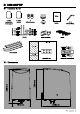
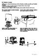
ABLOCAGE / INSTALLATION C1Installation de I'automatisme (1) Fou charognarde 12v (2) Phaacollues fen option) (3) Motorisation ds polar 12V (4) Télécommande 4 canaux Ne pas oublier de poser des butées physiques {non roumies) pour le bon fonctionnement du portail G2Tableau de dimensions Pour une installation correcte, conformez-vous scrupuleusement aux mesures indiquées sur le tableau dessous. Si nécessaire, ajuster la structure du portail pour "adapter & votre motorisation.
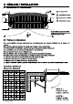
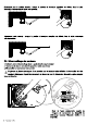
C3Fixation du moteur 1. Référez-vous au tableau de dimensions pour choisir les dimensions et positions appropriées pour installation des moteurs. 2. Tarifiez que la surface de montage des plaques de fixation soit lisse, verticale et rigide. 3. Disposez les fils d"alimentation des moteurs. 4. Montage du moteur et réglage des butées mécaniques dans las positions devanture et de fermeture.
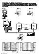
Ajustement pour la position fermée : lorsque la position de fermeture complété est définie, fixez la buée mécanique correspondante dans cette position. Ajustement porta ouverte : lorsque la position d’ouverture complote est définie, fixez la butée mécanique correspondante. C4Déverrouillage des moteurs 1. Insérez la clé dv déverrouillages dans la partie sous le moteur 2. Touez la clé dans le sens horaire jusqu'a la butée sans forcer 3. Déverrouillez et manœuvrez vautra portail.
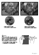
Position du moteur verrouillé : Position du moteur déverrouillé : Le téton doit tre en position ressortie La ton doit trait en position enfoncée Lx Astuce Au lieu de déverrouiller votre mateur & la force — 7 des bras, vous avez la possibilité d'utiliser une C \Vers moteur batterie en branchant dessus les fils moteur blanc et jaune dans un sens ou dans Faure suivant la polarité pour actionner les moteurs. Les fils jaunes et blancs doivent &tre = disconnecteur de la carte électronique.
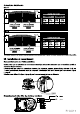
Ouverture Intérieure Cas n®1 ouvre en second ouvre an premier branchement sur branchement sur ouvre en premier ouvre en second branchement sur branchement sur Le moteur martre st le moteur esclave peuvent être installés sur le pilier de droite comme sur le plier de gauche.
DREGLAGE/UTILISATION Déréglage nombre de battants {dip Switch 1) Réglages dos pitchs : la position «DNs se situe vers le bas. «OFF» cors le haut.
D10Processus d"apprentissage du système pour un portail simple battant Positionnez le Switch 1 sur OFF. Positionnez le battant complètement ouvert. Pressez sur la touche « SIS-leam » {jusqu'a ce que le voyant LEDE clignote 1 fois par seconde au lieu de 2 fois par seconde comme il |e fait normalement, puis pressez la touche an haut droits ds la commandement pour Apprentissage d'un seul battant.
Photocellules (en option) Méthane de détection Faisceau infrarouge Portia 10M maximum Tension d'entrée 12-24V ACCORD Délai de réponse <100ms Indicateur de fonctionnement RX: LED rouge allumé { faisceau interrompu) LED rouge &teints {faisceau aligné} TX: LED rouge allumée {alimentation} Dimensions 63x 63x30 mm Type de sortie Sortie relais maintenance Effectuer [ss opérations suivantes au moins tous les 6 mois. En cas d'utilisation fréquents, raccourcir ce délai.
Un vantail se ferme jusqu'en butée et 1. Vérifiez si le battant ou vantail peut &tre manipulé librement et si aucun Faure s’arrise. obstacle n'est présent entre les deux. 2 Assurez-vous qua les câbles de connexion du moteur sont correctement raccordés. 3. Vérifias Fêtât de vautra fusible. 4. Assurez-vous que le faisceau de sécurité fonctionne. 5. Coupez l’alimentation de votre moteur et assurez-vous que les battants ou vantaux peuvent librement bouger paras les avoir débrayes. 6.
TABLE OF CONTENTS Safety Instructions 17 B Description. 18 Contents B2 Dimension: C Wiring / Installing C1 Standard installation. C2 Dimension chart C3 Motor fixing C4 Emergency reseal: C5 Wiring diagram C6 Installing & connecting D Setting / Using. E Technical features. F Maintenance &Technical assistance H Warranty Gloamings. SAFETY INSTRUCTIONS A WARNING: Important safety i instructions.
WIRING / INSTALLING Standard installation (1) voc inks (2) Photocells option ® 12V DC gate opener @ Re mats contra Do not forget to place physical stoppers {not Subpoenaed or tho proper functioning of the gate. Dimension chart Comply with the measures shown on the chart for proper installation. Adjust the gate structure to fit it for best automation, if necessary. Before starting the installation, please make sure that the gate moves freely and that : 1} Hinges are properly positioned and greased.
Motor fixing 1. Refer to the Dimension Chart to choose the correct dimensions of the motors and position. 2. Check if the mounting surface of the brackets to be installed is smooth, vertical and rigid. 3. Am range the cables for power supply cable of the motors. 4, Motor installation and setting for mechanical stopper in opened and closed position. 1) Remove the upper cover and mechanical stoppers 2) Place the gate in the full closed position and fix on the bottom of motor.
5) Closed position adjustment: 4.1 Once the full closed position is decided, (fix the corresponding mechanical stopper in this position. 8) Opened position adjustment : 5.1 Adjust the gate ta full opened position and once the position is decided, fix with corresponding mechanical stopper. Emergency release 1. Insert tha release key to the release slot 2. Tum the release key clockwise 3. Release and move the gate * At the beginning you may notice that the motors are difficult to release.
Position of locked motor : the pointless should be exited Fo Instead of unlock the motor with arms strength, you can use the battery connecting the white and yellow motor cables one way or the other following tha polarity to operate the mayors. fi The white and yellow cables must be disconnected from the electronic card.
Inside opening Casein opens first connection to opens first opens second connection to ‘connection to The master and slave motors can be installed on the right or on the left pillar. Uninstalling Power supply connections Please kindly notice that the operation of prows connection should be carried out by a qualified electrician with following steps : 1) Make sure the reformatory is not connected to the power supply before the installation is done. 2) Make sure all the wires are firmly connected.
Photocells (option ref. VAMOOSE) The photocells are safety devices for control automatic gates. Consist of ons transmitter and one receiver based in waterproof covers; iris triggered while breaking the path of the beams. Hf an obstacle is detected, the gate stops and opens again slightly allowing the obstacle to ba released safely.
TRENDSETTING Troubleshooting gate setting (dip switch 1) Switch tastings: =om» bottom position, xoff= top position.
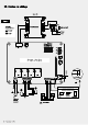
DOLED indication LED 1 System Learning: LED will ba on when remote controls are activated. LED 2 System loaning: LED 2 blinks twice per second during normal operation and once per second during learning. Static LED means incorrect programming. LED 3 Photocells: LED 3 will ba on when photocells are not aligned or when there's an ELECTRONIC CARD obstacle in between. LED start: LED # will ba on if the switch of the transmitter, key selector, or the push button is activated.
Subsystem learning process for single leaf gate Switch 1 OFF. Pan the leaf totally. Press «SAYS-learn (until the LED light begins to flash once every secant, instead of twice every second as it normally would), then pass the upper-right key for a single gate.
Photocells (option) Detection Method infrared beam Sensing Manga Maxima Input Voltage 12-24 V AC/DC Response Tums <100ms Operation Indicator RX: Red LED On {baa broken) / Off {beam aligned) TX: Red LED On Di mansions 63x 63x30 mm Output Method relay output Remote controls Ch annals 4 Frequency Maximum transmitted power 433.92 MHz prows < 10 mW Power supply 2 batteries lithium CR2016 included Security rolling code technology MAINTENANCE Conduct the following operations at least every 6 months.
TECHNICAL ASSISTANCE Troubleshooting Problem Solutions Overheated back-up batteries Check the wiring connection of the batteries. ‘The gate doesn't move when pressing the bunion of the transmitter Tha transmitting distance is too short ‘Tha flashing light doss not work 1. Check if LED is "ON" acne pressing the transmitter. 2. Checkif the voltage of the batteries is above 12V. 3. Check if LED is "ON" and blinks accordingly. 4.