SDT ARK 1 ECHO Software Defined Transposer / Re-Transmitter Gap Filler / Echo canceller OPERATION MANUAL Jan 2012 - Version 1.ATSC_FCC_ © 1997 - 2012. Copyright by: Screen Service Broadcasting Technologies S.p.A. Via Giuseppe Di Vittorio, 17 25125 Brescia, Italy All rights reserved. All specifications, characteristics and circuit descriptions set forth in this manual are subject to change without notice.
SDT ARK 1 ECHO Software Defined Transposer / Re-Transmitter Gap Filler / Echo canceller OPERATION MANUAL Jan 2012 - Version 1.ATSC_FCC © 1997 - 2012. Copyright by: Screen Service Broadcasting Technologies S.p.A. Via Giuseppe Di Vittorio, 17 25125 Brescia, Italy All rights reserved. All specifications, characteristics and circuit descriptions set forth in this manual are subject to change without notice.
Screen Service SDT ARK 1 ECHO Contents SDT ARK 1 ECHO Software Defined Transposer / Re-Transmitter Gap Filler / Echo canceller OPERATION MANUAL LIST OF CONTENTS CHAPTER 1: GENERAL INFORMATION Gives information on safety procedures and good practices to follow using the equipment. CHAPTER 2: PURPOSE AND PLANNING Introduction to the manual, technical specifications, brief functional description with block diagram.
Screen Service SDT ARK 1 ECHO General information SDT ARK 1 ECHO Software Defined Transposer / Re-Transmitter Gap Filler / Echo canceller OPERATION MANUAL 1 GENERAL INFORMATION CONTENTS 1.1 SAFETY SUGGESTIONS ...................................................................................................................... 2 1.2 GENERAL SAFETY RECOMMENDATIONS ......................................................................................... 3 1.3 GOOD PRACTICES ...............................
Screen Service SDT ARK 1 ECHO General information 1.1 SAFETY SUGGESTIONS Regardless of how well electrical equipment is designed, personnel can be exposed to dangerous electrical shock when protective covers are removed for maintenance or other activities. Therefore, it is incumbent on the user to see that all safety regulations are consistently observed and that each individual assigned to the equipment has a clear understanding of the first aid related to electrical shocks.
Screen Service SDT ARK 1 ECHO General information 1.2 GENERAL SAFETY RECOMMENDATIONS When connecting the equipment to the power, please follow these important recommendations: This product is intended to operate from a power source that will not apply more than 10% of the voltage specified on the rear panel between the supply conductors or between either supply conductor and ground. A protective-ground connection by way of the grounding conductor in the power cord is essential for safe operation.
Screen Service SDT ARK 1 ECHO General information 1.4 PROCEDURE FOR ESTABLISH THE ABSENCE OF VOLTAGE Follow these simple steps for establish the absence of voltage: Before starting work on the equipment, it shall be isolated from the mains supply. This disconnection shall always be checked by visual inspection. Further precautions shall be taken to ensure that the mains supp!y cannot be restored whilst work is being carried out.
Screen Service SDT ARK 1 ECHO General information 1.5 FIRST AID IN CASE OF ELECTRICAL SHOCK If someone seems unable to free himself while receiving an electric shock, turn power off before rendering aid. A muscular spasm or unconsciousness can make a victim unable to free himself from the electrical power.
Screen Service SDT ARK 1 ECHO General information Step 5 Position your hands in the center of the chest between the nipples. Place one hand on top of the other. Step 6 Push down firmly two inches. Push on chest 15 times. CONTINUE WITH TWO BREATHS AND 15 PUMPS UNTIL HELP ARRIVES. 1.5.2 TREATMENT FOR BURNS Continue treat victim for electrical shock. Check for points of entry and exit of current. Cover burned surface with a clean dressing.
Screen Service SDT ARK 1 ECHO General information 1.5.3 ELECTRIC SAFETY PRECAUTIONS All the parts making up the equipment have got danger identification tags (with a yellow background) to highlight the parts dangerous for the operator that has access to the system. Presence of hazardous energy levels A hazardous energy level is defined as a stored energy level of 20 J or more, or an available continuous power level of 240 VA or more, at a potential of 2 V or more. 1.5.
Screen Service SDT ARK 1 ECHO General information 1.6 R&TTE DIRECTIVE 1999/5/EC Declaration of Conformity with regards to the R&TTE Directive 1999/5/EC English: This equipment is in compliance with the essential requirements and other relevant provisions of Directive 1999/5/EC Deutsch: Dieses Gerät entspricht den grundlegenden Anforderungen und den weiteren entsprechenden Vorgaben der Richtlinie 1999/5/EU.
Screen Service SDT ARK 1 ECHO General information 1.7 WASTE ELECTRICAL AND ELECTONIC EQUIPMENT (WEEE) The purpose of the DIRECTIVE 2002/96/EC OF THE EUROPEAN PARLIAMENT AND OF THE COUNCIL of 27 January 2003 on waste electrical and electronic equipment (WEEE) is, as first priority, the prevention of waste electrical and electronic equipment and, in addition, the reuse, recycling and other forms of recovery of such wastes so as to reduce the disposal of waste.
Screen Service SDT ARK 1 ECHO Purpose and planning SDT ARK 1 ECHO Software Defined Transposer / Re-Transmitter Gap Filler / Echo canceller OPERATION MANUAL 2 PURPOSE AND PLANNING CONTENTS 2.1 GENERALITY ......................................................................................................................................... 3 2.2 INTRODUCTION .................................................................................................................................... 3 2.2.
Screen Service SDT ARK 1 ECHO Purpose and planning 2.5.6 MANAGEMENT ............................................................................................................................. 13 2.5.6.1 GIGABIT ETHERNET ............................................................................................................ 13 2.5.6.2 REAR SUB-D 25P CONNECTOR ......................................................................................... 14 2.6 FUNCTIONAL DESCRIPTION ......................
Screen Service SDT ARK 1 ECHO Purpose and planning 2.1 GENERALITY Propagation is a critical issue in ATSC / Mobile TV broadcasting. In this contest, the use of repeaters for digital TV broadcasting becomes a key issue for commercial terrestrial distribution of digital TV. In addition, 8VSB signal characteristics avert well known adjacent channel interference problems of analogue TV broadcasting.
Screen Service SDT ARK 1 ECHO Purpose and planning 2.2.2 DIGITAL TELEVISION HETERODYNE TRANSPOSER WITH ECHO CANCELLER Heterodyne Transposer with Digital Filtering at Intermediate Frequency for Analog and Digital Television standards. Capable of: Agile UHF input Down-converter (from 470 MHz up to 862 MHz). Agile UHF output Up-converter (from 470 MHz up to 862 MHz). Input Analog/Digital signal level monitoring with quality measurement for ATSC Digital Filtering at Intermediate Frequency.
Screen Service SDT ARK 1 ECHO Purpose and planning 2.2.4 FUNCTIONAL BLOCK DIAGRAMS Echo board block diagram Sat RX o Down converter alternativi Figure 1 960 960 120 146 Down Conv.
Screen Service Figure 2 SDT ARK 1 ECHO Purpose and planning Echo down-converter block diagram Mix Ch Flt ADL SAW MGA IF_Out RF Out Lo 146M ADF vc o Alim FeedBack A Fw Out A Peak FW Detect RMS Fw Detect A A RMS Drv Detect A Ph Drv Forw. A Ser ARM ADUC + Detect Reflect RMS Ref Detect Detect Peak Drv Jan, 2012 v 1.
Screen Service Figure 3 SDT ARK 1 ECHO Purpose and planning Echo 2 up-converter block diagram Mix Ch Flt ADL SAW MGA IF_Out RF Out Lo 146M ADF vc o Alim FeedBack A A Peak FW Fw Out Detect RMS Fw Ph Drv A ARM ADUC RMS Drv A Detect Ser Forw. Detect PWM A A RC + Detect Reflect RMS Ref Detect Detect Peak Drv Jan, 2012 v 1.
Screen Service SDT ARK 1 ECHO Purpose and planning 2.3 PURPOSE This manual contains information and reference documentation on installation, operation and maintenance of the SDT ARK 1 equipment. 2.
Screen Service SDT ARK 1 ECHO Purpose and planning 2.4.1 FRONT AND REAR PANEL FUNCTIONS LIST On the front panel are located the following functions/connectors (from left to right) 1. 2. 3. 4. 5. 6. 7. 8. 9. 10. RF INPUT GPS INPUT ASI OUTPUT HP ASI OUTPUT LP ASI INPUT 1 ASI INPUT 2 ASI INPUT 3 ASI INPUT 4 GBE DISPLAY & NAVIGATION 1 1 Jan, 2012 2 3 4 2 3 4 5 6 7 8 9 5 6 7 8 10 9 v 1.
Screen Service SDT ARK 1 ECHO Purpose and planning On the rear panel are located the following functions/connectors (from left to right) 1. 2. 3. 4. 5. 6. 7. 8. 9. AC MAIN INPUT & ON/OFF SWITCH AC/DC FAN GROUND REFERENCE AUX REMOTE 10 MHz INPUT 1 PPS INPUT FANs EQUIPMENT COOLING (a & b) RF OUTPUT RF MONITOR 1 2 3 4 5 6 7a 7b 8 9 10. 11. 12. 13. 14. 15. 16. 17.
Screen Service SDT ARK 1 ECHO Purpose and planning 2.5 TECHNICAL PERFORMANCE 2.5.1 GENERAL Available standards ATSC Operating frequency range VHF Band I: 45 - 90 MHz VHF Band III: 174 - 260 MHz UHF Band IV & V: 470 - 860 MHz IF Frequency IF Bandwidth Time delay ECHO Delay correction capability (Equipment time delay NOT included) Correction speed 36 MHz +/- 4 6 -7- 8 MHz (TBS) 7 us typ.
Screen Service SDT ARK 1 ECHO Purpose and planning 2.5.3.3 GPS Input connector Antenna power supply Sensitivity TNC female from transmitter, 5V DC -185dBW 2.5.3.4 10 MHz Input connector Input Impedance Level BNC female 50 Ohm 2 Vpp 2.5.3.5 1 PPS Input connector Input Impedance Level Pulse width BNC female 50 Ohm TTL 100us 2.5.3.6 OPTOCOUPLERS (4) Input connector Max current SUB-D 25p Female -5 mA 2.5.4 OUTPUT PARAMETERS 2.5.4.
Screen Service SDT ARK 1 ECHO Purpose and planning 2.5.4.5 RELAYS N° outputs Connectors Max voltage Modes (TBD) 4 SUB-D 25p Female 125VAC / 60VDC @ 0,3A 30VDC @ 1A Relay 0: o Alarm mask: Off: no alarms; On: one or more alarm o Mode: Off: Mode A; On: Mode B. Relay 1: o Alarm mask: Off: no alarms; On: one or more alarm o Mode: Off: Mode A; On: Mode B.
Screen Service SDT ARK 1 ECHO Purpose and planning 2.5.6.2 REAR SUB-D 25P CONNECTOR N° connectors Connector Pinout Jan, 2012 1 2 3 4 5 6 7 8 9 10 11 12 13 14 15 16 17 18 19 20 21 22 23 24 25 1 SUB-D 25p Female N.C. IN_OPTO_1 IN_OPTO_2 IN_OPTO_3 OPTO_GND N.C. N.C. N.C. RS232 Tx RS232 Rx N.C. IN_OPTO_0 N.C. N.C. N.C. FWD_OUT RL_COM0 RL0 RL_COM1 RL1 RL_COM2 RL2 RL_COM3 RL3 RS232 GND v 1.
Screen Service SDT ARK 1 ECHO Purpose and planning 2.6 FUNCTIONAL DESCRIPTION 2.6.1 GENERAL The ARK 1 receives on its inputs An RF signal or four MPEG-2 Transport Stream in serial ASI format. The RF input signal is converted into a standard 36 MHz IF frequency by a fully agile down converter. This signal is digitally filtered, elaborated, precorrected and then presented at 997 MHz to the channel converter. The channel converter provides to generate the final frequency in a fully agile mode.
Screen Service SDT ARK 1 ECHO Operations SDT ARK 1 ECHO Software Defined Transposer / Re-Transmitter Gap Filler / Echo canceller OPERATION MANUAL 3 OPERATIONS CONTENTS 3.1 INSTALLATION ...................................................................................................................................... 3 3.1.1 INSTALLATION PROCEDURE CHECK OFF ..................................................................................... 3 3.1.2 SITE SELECTION .....................................
Screen Service SDT ARK 1 ECHO Operations 3.5.3 Connection to port 5000 ............................................................................................................. 55 3.6 Channel filter & complex filter ........................................................................................................... 56 3.6.1 OUTPUT ............................................................................................................................................ 62 3.7 NETWORK .........
Screen Service SDT ARK 1 ECHO Operations 3.1 INSTALLATION 3.1.1 INSTALLATION PROCEDURE CHECK OFF Some procedures in this section contain steps preceded by a check box. Fill out or initial each step as it is completed. 3.1.2 SITE SELECTION Use the following specifications to establish criteria for site selection and equipment installation. 3.1.2.1 MOUNTING SPECIFICATIONS Mount.
Screen Service SDT ARK 1 ECHO Operations 3.1.4 EQUIPMENT MOUNTING Install the transmitter in an EIA (Standard 310) 19 inch rack as follows: Place the equipment into the rack (2 units), align the mounting holes, and secure in place with four rack screws. If configured to operate, make sure the "LINE" switch on the front panel of the POWER SUPPLY & METERING module is OFF. Connect the power cord to an operating power source.
Screen Service SDT ARK 1 ECHO Operations 3.1.5 FRONT PANEL 1 2 3 4 5 6 7 8 9 10 ARK 1 Front Panel n. 1 Label RF INPUT Description 2 GPS IN 3 ASI OUTPUT HP 4 ASI OUTPUT LP 5 ASI in 1 6 ASI in 2 7 ASI in 3 8 ASI in 4 9 GBE 1 10 LCD Display 3.1.5.1 REAR PANEL 1 2 3 4 5 6 7a 7b 8 ARK 1 Rear Panel n.
Screen Service SDT ARK 1 ECHO Operations 3.1.5.2 REAR PANEL CONNECTORS AUX REMOTE CONNECTOR Sub-D 25 Male. PIN 1 2 3 4 5 6 7 8 9 10 11 12 13 14 15 16 17 18 19 20 21 22 23 24 25 ASSIGNMENT Not used Alarm reset Remote STBY GND OPTO REMARKS in opto active to gnd in opto active to gnd SERIAL 485/232 SERIAL 485/232 RF OFF in opto active to gnd COM RL 0 RL 0 COM RL 1 RL 1 COM RL2 RL 2 COM RL 3 RL 3 NOR. CLOSED NOR. CLOSED NOR. CLOSED NOR. CLOSED Figure 3.1-1: AUX REMOTE CONNECTOR Jan, 2012 v 1.
Screen Service SDT ARK 1 ECHO Operations 3.1.6 MULTIMETER The following paragraphs describe the local user interface for ARK1. This user interface is composed of LCD Display, seven buttons and two status leds. Here below is depicted the ARK1 Front Panel. ESCAPE ON ALARM STANB-BY OK LEFT ARROW RIGHT ARROW UP ARROW DOWN ARROW Jan, 2012 STAND-BY: push this button (lie in wait for two seconds) to put the equipment on STAND-BY mode.
Screen Service SDT ARK 1 ECHO Operations 3.1.7 LOCAL INTERRFACE MENU TREE Figure 1.
Screen Service SDT ARK 1 ECHO Main display menu Operations LEGEND Menu System status Multiple choice Tuner Data R Tuner HP Lock status Data W Demodulator BER Viterbi BER Packet errors SNR Constellation Hierchical Mode Interleaver FEC FFT Guard Time Cell ID Tuner LP Lock status Demodulator BER Viterbi BER Packet errors SNR Constellation Hierchical Mode Interleaver FEC FFT Guard Time Cell ID Output Output RF status Frequency ref Channel Offset FWD power RFL power RTP 1 Input IP Address Status
Screen Service SDT ARK 1 ECHO Main display menu Operations LEGEND Menu System status Multiple choice Modulation Data R Network Data W Del Null Pcks Bandwidth Constellation Hierarchical Mode Interleaver HP FEC LP FEC FFT Guard Time Cell ID Time Slice HP Time Slice LP MPE FEC HP MPE FEC LP Alarms Alams list Reset system Yes No Change mode Mode A Mode B Jan, 2012 v 1.
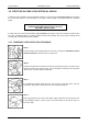
Screen Service SDT ARK 1 ECHO Operations 3.1.8 BOOT AND WELCOME MESSAGE Turning on the equipment, the display shows the progress bar as follow: Screen Service ARK - ATSC/DIG-IF System Init Init : [ ] Screen Service ARK - ATSC/DIG-IF Up Converter check Init : [ ] Wait Screen Service ARK - ATSC/DIG-IF Boot FPGA Init : [ ] Wait Wait Screen Service ARK - ATSC/DIG-IF Start system Init : [ ] Wait When the boot is over, the board is ready.
Screen Service 3.2 SDT ARK 1 ECHO Operations IDLE MENU ARK -DIGITAL-IF (DIG) DIn 23.1dBm CH:22 Dout 23.1dBm CH:22 UTC: 14:11 08/11/06 ARK - ATSC InHP: ASI1 Out 17.1dBm CH:22 UTC: 14:11 08/11/06 ARK -DIGITAL-IF (ANA) AIn 23.1dBm CH:22 Aout 23.1dBm CH:22 UTC: 14:11 08/11/06 This menu appears after one minute waiting from the last touch. Information contained in the Idle Menu are described in next table. Table 1.
Screen Service SDT ARK 1 ECHO Operations 3.2.1 MAIN MENU Change Mode Network setup System Status / / OK:Enter This menu shows five SUBMENUS. It is possible to view them sliding the menu up and down, with the UP or DOWN ARROWS, and to select one of them by pushing on the OK button. Submenus contained in the Main Menu are described in next table.
Screen Service 3.3 SDT ARK 1 ECHO Operations LCD alarms Through the LCD Alarms mask it is possible to select which alarm has to be notified on LCD display. The alarm button is lighted and when an alarm condition occurs, alarms status is displayed in the Alarms submenu. The following table lists the alarms messages displayed on LCD, associated to the corresponding alarm (refer to Alarms paragraph for further information about alarms and their masks). Alarms descriptions list Table 2.
Screen Service SDT ARK 1 ECHO Alarm Alarm Message ATSC No Input In. not detected FPGA Boot alarm FPGA boot err Warm up alarm Sys. warm up Jan, 2012 Operations v 1.
Screen Service SDT ARK 1 ECHO Operations 3.4 JAVA REMOTE GRAPHIC USER INTERFACE The Java Graphic User Interface, stored in the board File System, is downloaded to the local PC every time the user connects to the board with a Web Browser. A proper Java Virtual Machine is needed; refer to the Appendix B for a description of supported Java and Internet Browsers. 3.4.1 JAVA INTERFACE OVERVIEW The following figure shows the main control switch of the Java User Interface.
Screen Service SDT ARK 1 ECHO Operations Figure 3. System commands bar Operation pages bar allows to switch between the following operative sections: General: allows the enable the Stand-by mode through the LCD Button, to reset the device and to locally download the *.jar file. Input: shows ASI and GBE input statistics (Re-broadcasting Hierarchical ATSC Modulator).
Screen Service SDT ARK 1 ECHO Operations 3.4.1.1 General Click on General button icon, highlighted in the nex figure, to access the general window. Figure 6. General window The General window provides a general description of the device and allows the access to a subset of commands through the following button icons: Reset: resets the device. LCD Standby: enables the LCD Stand-by button. Download Software Standalone: performs a local download of the *.
Screen Service SDT ARK 1 ECHO Operations 3.4.1.2 Input Click on Input button icon, highlighted in the nex figure, to access the input statistics window. Figure 7. Input window The Input window allows the monitoring of auxiliary inputs of Re-broadcasting ATSC Modulator. Input Transport Stream monitoring of four ASI and two RTP channels on GBE port are provided. Jan, 2012 v 1.
Screen Service SDT ARK 1 ECHO Table 3. Box Parameter / Control ASI Word rate ASI Bitrate [bit/s] Operations Input window Description Admitted Ranges / Values ASI input word rate. 10 bit word rate of ASI input (Ref. to CEI EN 50083-9). Approximately 27 Mword/s ASI input bitrate. R/H R R Zero when the input is not selected Equal to the total bitrate, when Delete Filtered ASI Bitrate actually used by the modulator.
Screen Service Box Parameter / Control ASI Word Errors SDT ARK 1 ECHO Operations Description Admitted Ranges / Values Total amount of ASI wrong words received. R/H R UDP RTP Protocol Ethernet input packets protocol. R RTP RTP Bitrate [bit/s] Bitrate of TS from Ethernet input. R Zero when the input is not selected Equal to the total bitrate, when Delete Filtered RTP Bitrate actually used by the modulator.
Screen Service Box Parameter / Control SDT ARK 1 ECHO Operations Description Admitted Ranges / Values R/H Red: Alarm on GbE input overflow alarm status. This alarm condition occurs when the input bitrate exceeds the RTP Overflow capability of the modulation (Ref. to ETSI EN 300 744). R Grey: Alarm off RTP GBE packets Total amount of good Ethernet frames received. R 10 Mbit//s RTP Speed Ethernet connection speed. No duplex information is provided.
Screen Service SDT ARK 1 ECHO Operations 3.4.1.3 TUNER Click on Tuner button icon, highlighted in the nex figure, to access the tuner window. Figure 8. Tuner window This window provides commands that allow the selection of working modes, the management and selection of inputs, and the monitoring of quality and level of input RF signals.
Screen Service SDT ARK 1 ECHO Operations Table 4. Box Parameter / Control Modes management Description Admitted Ranges / Values R/H System Mode & Mode A Actual mode Current operating mode. Autoswitching R/H Mode B System Mode & Mode A Manual Selector of mode used when Manual Switch mode is selected. Autoswitching R/H Mode B Selector of the switch mode rules.
Screen Service Box SDT ARK 1 ECHO Parameter / Control Operations Description Admitted Ranges / Values R/H Out of range: input frequency error exceeds 166 KHz dynamics. Set a +/166 KHz input freq. offset in order to System Mode & Frequency Frequency error automatically corrected. Autoswitching Error [Hz] Note: When the frequency error exceeds the dynamics, STV might loose the lock. System Mode & Automatic true up the dynamics.
Screen Service SDT ARK 1 ECHO Box Parameter / Control Mode A / Mode B Channel Operations Description Admitted Ranges / Values Mode A / Mode B Offset [Hz] Squelch Mode A / Mode B Mode A / Mode B Jan, 2012 Input HP Input LP Min: 21 Selector of the UHF input channel used as RF input. R/H Max: 69 Min: -4 MHz Frequency offset from the channel center frequency of the RF input. 1 Hz step variation. Squelch alarm threshold expressed in dBm.
Screen Service Box SDT ARK 1 ECHO Parameter / Control Operations Description Admitted Ranges / Values R/H No RF, No TS Switching modes rules Input, Tuner Switching Rules S/N, Input Mode A / B Squelch, Tuner Autoswitch alarms mask. Refer to paragraph for a detailed description of the switching rules and conditions. BER Jan, 2012 v 1.
Screen Service SDT ARK 1 ECHO Operations 3.4.3 Modes switching rules Four switching rules are provided in order to cover different requirements: Manual: switch between mode A and mode B by selecting one mode using the Manual Selector. The selected mode is always enabled until the user selects the other one. Auto: switch between mode A and mode B using the rules shown in the following table.
Screen Service SDT ARK 1 ECHO Operations 3.4.4 Tuner management These commands allow the setting of BER alarm threshold and monitoring of RF input status. The following table shows all the commands and indicators available. Jan, 2012 v 1.
Screen Service SDT ARK 1 ECHO Table 6. Box Parameter / Control Tuner Stat Bitrate [bit/s] Operations Tuner management Description Admitted Ranges / Values Bitrate of TS from RF input (HP and LP). R/H R/H Zero when the input is not selected Equal to the total bitrate, when Delete Tuner Stat Filtered [bit/s Bitrate actually used by the modulator. Null Packets disabled R/H Less than total bitrate, when Delete Null Packets enabled HP/LP input lock status.
Screen Service Box Parameter / Control SDT ARK 1 ECHO Description Admitted Ranges / Values Squelch Turner Main R/H Analog signal lock status. The PAL detector has been implemented through the detection of the video Grey: No alarms Green: Good Analog V Sync R/H carrier synchronization at 15,625 Hz. HP/LP Receiver Demodulator Statistics BER R/H Red: Alarm Squelch alarm status. alarm Turner Main Operations Grey: Bad Analog Demodulator bit error rate.
Screen Service Box Parameter / Control SDT ARK 1 ECHO Description Admitted Ranges / Values HP/LP Receiver Hier. Mode NH a=1 Hierarchy information for current scheme. R/H R/H Statistics HP/LP Receiver Interleaver Operations a=2 a=4 Native Interleaver type. R/H Statistics In-depth 1/2; 2/3; 1/4; 5/6; 7/8. 2K; 4K; 8K. HP/LP Receiver FEC HP/LP stream code rate. Statistics R/H HP/LP Receiver FFT Transmission mode.
Screen Service Box Parameter / Control SDT ARK 1 ECHO Description Admitted Ranges / Values HP/LP Receiver Guard Time Operations 1/32; 1/16; Guard interval. R/H R/H Statistics 1/8; 1/4. HP/LP Receiver Cell ID Cell ID R/H TPS were confirmed decoded. R/H Symbol recovery loop locked. R/H Statistics HP/LP STV Lock TPS Symbol HP/LP STV Lock Recovery Green: Locked; Grey: Not locked. Puncture HP/LP STV Lock Puncture rate found.
Screen Service SDT ARK 1 ECHO Operations 3.4.5 MODULATION Click on Modulation button icon, highlighted in the nex figure, to access the modulation window. Figure 9. Modulation window: modulation parameters The Modulation window allows actual modulation parameters monitoring and modulator setting/monitoring. These settings are always editable but are applied only when the remodulator working mode is enabled. 3.4.
Screen Service SDT ARK 1 ECHO Table 7. Box MFN / SFN Parameter / Control MFN/SFN Modulation management Description Admitted Ranges / Values Selector of Network‟s Transmitters Synchronization. Network Synchronization parameter setting Refer to MFN MFN MIP R/H R paragraph. Delete null packets enabling check box. Delete Null MFN / SFN Operations SFN SFN Local Checked: Enabled In SFN and SFN Local transmission modes, this option is enabled by default.
Screen Service Box Parameter / Control SDT ARK 1 ECHO Operations Description Admitted Ranges / Values R/H Alarms MIP Alarm Mip Detection Delay [s] Time to wait for No MIP alarm rising expressed in seconds (refer to paragraph). Min: 1 s R Note: It is highly recommended to set a MIP Alarm Delay value different from zero as to allow the input signal locking. Force Null Test Max: 25.5 s Checked: Enabled Null data packets transmission enabling check box.
Screen Service SDT ARK 1 ECHO Operations 3.4.7 Network Synchronization parameters setting Four Network Synchronization modes are available: Multi Frequency Network mode using local parameters (MFN): The transmitter is not synchronized with any network. No input MIP is needed and Clock Reference can be internal. Multi Frequency Network mode using MIP parameters (MFN MIP): The transmitter is not synchronized with any network but MIP sets the modulation parameters.
Screen Service Parameters SDT ARK 1 ECHO Operations MFN SFN MFN + MIP Time Offset Local MIP or Local (only if enabled) Function from MIP can be enabled or disabled Del Null Packet Frequency Reference Can be enabled or disabled Can be internal or external MIP or Local (only if enabled) Function from MIP can be enabled or disabled Can be enabled or disabled Can be internal or external Must be disabled Must be external SFN Local Local Must be disabled Must be external 3.4.
Screen Service SDT ARK 1 ECHO Table 9. Box Parameter/ Control MIP Modulation parameters Description Admitted Ranges / Values Transmission mode: set by MIP. Local Actual R 4K 8K 7MHz 8MHz 6MHz 5MHz Current bandwidth. MIP Constellation for current modulation scheme: set by MIP. Local R Bandwidth: set by MIP. Actual R R QPSK 16-QAM 64-QAM 7MHz R Constellation for current modulation scheme: locally set.
Screen Service Box Parameter/ Control Actual SDT ARK 1 ECHO Description Admitted Ranges / Values Current bandwidth. MIP HP/LP stream code rate: set by MIP. Local HP/LP stream code rate: locally set. 8MHz 6MHz 5MHz 1/2 R R 2/3 3/4 5/6 7/8 NH; Current HP/LP stream code rate. MIP Hierarchy information for current scheme: set by MIP. Local Hierarchy information for current scheme: locally set.
Screen Service Box Actual Parameter/ Control SDT ARK 1 ECHO Operations Description Admitted Ranges / Values Current guard interval. Jan, 2012 v 1.
Screen Service SDT ARK 1 ECHO Operations 3.4.9 ATSC parameters These commands and indicators allow the setting of options for ATSC transmission, the monitoring of parameters carried by MIP in SFN configuration and of actual ATSC options. Figure 12. Jan, 2012 ATSC parameters v 1.
Screen Service SDT ARK 1 ECHO Operations ATSC parameters. Table 10. Box Parameter/ Control MIP Admitted Ranges / Values Description Enabling of time slice transmission of the HP/LP stream: set by MIP. Time Slicing Local R Current enabling status of time slice transmission. MIP HP/LP MPE-FEC enabling: set by MIP. MPE FEC Local Actual Current HP/LP MPE-FEC enabling status. MIP Interleaver type selector: set by MIP. Actual Not used Used R R HP/LP MPE-FEC enabling: locally set.
Screen Service SDT ARK 1 ECHO Operations 3.4.10 MIP functions These commands and indicators allow the enabling and monitoring of MIP functions in SFN configuration, the setting of local functions and the monitoring of the actual functions used by modulator. Figure 13. Jan, 2012 MIP functions v 1.
Screen Service SDT ARK 1 ECHO Operations MIP function Modulation window: MIP functions Table 11. Box Parameter / Control MIP Description Admitted Ranges / Values MIP cell ID function enabling R/H R Checked: Enabled Cell Id enable Local General Cell Id enabling. Must be enabled to insert Cell Id into output TPS. R MIP MIP cell ID monitoring. R Local Not checked: Disabled Cell ID Min: 0 Local Cell ID setting. R Max: 65,535 Actual Used Cell ID monitoring.
Screen Service Box Parameter / Control SDT ARK 1 ECHO Operations Description Admitted Ranges / Values Local Min: -500,000 Hz User frequency offset setting. R Actual Max: 500,000 Hz Used frequency offset monitoring. R MIP R/H Checked: Enabled MIP time offset function enabling and monitoring R Not checked: Disabled Min: -32,768 Time Offset [100ns] Local User time offset setting. R Actual Max: 32,767 Used time offset monitoring.
Screen Service Box Parameter / Control SDT ARK 1 ECHO Operations Description Admitted Ranges / Values MIP Func.Bw Checked: Enabled NOT IMPLEMENTED (Function Bw enabling and monitoring). R Function Cell MIP R/H Not checked: Disabled Green: enabled MIP Cell ID function enabling status. R ID enabled Function Tag MIP Grey: disabled Green: present Cell ID Tag detection. R Cell ID.
Screen Service Box Parameter / Control SDT ARK 1 ECHO Description Admitted Ranges / Values Tx ID Local Broadcast Local Tx ID Standard R/H Checked: Enabled Tx ID 0 enabling. R Enable Local Operations Not checked: Disabled Min: 0 User Tx ID setting. R Max: 65,535 ATSC o Checked: Enabled o Not checked: Disabled User transmission standard setting. R ATSC o Checked: Enabled o Not checked: Disabled Center Freq. Actual Used center frequency indicator.
Screen Service Box Parameter / Control SDT ARK 1 ECHO Description Operations Admitted Ranges / Values R/H Network Delay Actual Used network delay indicator. R [100ns] s Table 12. Jan, 2012 v 1.
Screen Service 3.5 SDT ARK 1 ECHO Operations PRE-CORRECTION TOOL The ARK1 system provides a pre-correction tool for both Module&Phase and AM/PM output signal pre-correction. Remember to save curves changing before closing the connection to port 5000. At every working session open Note: the operation of uploading and downloading pre-correction curves moves a large amount of data from and to the device.
Screen Service SDT ARK 1 ECHO Operations This tool provides two grids for the drawing of: Module of the filter’s curve. Group Delay of the filter’s curve. The two curves are used to calculate the linear pre-correction coefficients. The curves are drawn by the interpolation of 1024 points referring to the points inserted and using a linear or polynomial interpolation algorithm.
Screen Service SDT ARK 1 ECHO Figure 15. Operations AM/PM window Two main actions are possible in this section: AM/AM and AM/PM curve drawing: used to change the AM/PM pre-correction coefficient. AM/PM pre-correction files management: used to open or save AM/PM precorrection setting file. AM/AM and AM/PM curves are specific for each power range of each output channel. The two curves are used to calculate the AM/PM pre-correction coefficients.
Screen Service SDT ARK 1 ECHO Operations The following buttons allow the management of linear pre-correction files and the management of the connection to port 5000: Save: used to save in the device memory the current curves setting. The previously saved file will be overwritten except in the evet that no files have been saved before; in this case a dedicated window appears in order to let the user name the new file. Save as: used to save in the device memory the current curves setting.
Screen Service SDT ARK 1 ECHO Operations 3.5.3 Connection to port 5000 The connection to port 5000 is performed every time a pre-correction tool is opened through Mod.Pha. button and AM/PM button, from Java interface,.
Screen Service 3.6 SDT ARK 1 ECHO Operations Channel filter & complex filter Click on Filter button icon, highlighted in the nex figure, to access the channel and complex filters window. Figure 17. Channel filter & complex filter window Use the Filter window to manage and monitor channel and complex filters. To understand the behavior of the Echo’s Channel Filter, a brief explanation is needed.
Screen Service SDT ARK 1 ECHO Operations It follows that: Thr. FB Alarm > Thr. FB Down > Thr. FB Up. The “FPGA Gain” value results from the comparison of the “Module” value with the thresholds: 0: when “Module” is lower than FB Up. 1: when “Module is higher than FB Down. 2: when “Module” is comprised between FB Up and FB Down. Jan, 2012 v 1.
Screen Service SDT ARK 1 ECHO Figure 18. Jan, 2012 Operations Filters commands and monitors v 1.
Screen Service SDT ARK 1 ECHO Parameter / Operations Admitted Ranges / Box Description R/H/E Control Values Red: Echo Correction Enables or disables the updating of the Echo Correction coefficients. When in “Echo Correction Started” Started/Stopped mode, the system continues calculating the Stopped General R coefficients, but those are not updated. Green: Echo Correction Started. System Indicates the running status of the echo canceling General Running/Locked General Clear Coeff.
Screen Service SDT ARK 1 ECHO Operations Indicates the value of the counter, incremented General Action Fast each time an Action Fast was performed. Introduced for debug purposes. Indicates the value of the counter, incremented General Action Slow each time an Action Slow was performed. Introduced for debug purposes. 0: when “Module” is lower than Thr. FB Up. 1: when “Module” is higher than General Indicates the actual value of the Foldback status. Thr. FB Introduced for debug purposes.
Screen Service Out Echo SDT ARK 1 ECHO Operations Indicates the value of the Echo amplitude that was General Residual [dB] not compensated. Indicates the value of the Echo amplitude that was General Input Echo [dB] compensated. General Import… Imports the “.echf” file that contains the channel R filter coefficients. Shows the same value as “fdback val” indicator. General Coeff.0 R Introduced for debug purposes.
Screen Service SDT ARK 1 ECHO Operations Specifies the peak value of the module of the 214748364 current filter‟s coefficients. to be considered as 8 Threshold Fold General Min: - lower level of the optimal range. The optimal range Back Up is determined by the “Threshold Fold Back Down” and “Threshold Fold Back Up” values.
Screen Service SDT ARK 1 ECHO Figure 19. Operations Output window Use the Output window to change and monitor both Ethernet and RF output settings, and to monitor all accessible hardware indicators. Jan, 2012 v 1.
Screen Service SDT ARK 1 ECHO Operations Output window Box Parameter / Control Description Admitted Ranges / Values R/H Output RF signal enabling. The possible output RF signal status are the following: RF RF ON; RF not On: automatic switch off of the output signal (refer to Ampli status); OFF: manual switch off of the output signal. ON / OFF Frequency reference Frequency reference source selector. Internal frequency reference fine tuning setting.
Screen Service Box SDT ARK 1 ECHO Parameter / Control Operations Description Admitted Ranges / Values AGC Mode Frequency Frequency Out [Hz] Out [Hz] R/H Analog/Digital: Current AGC mode indicator. o Green: ON o Grey: OFF R/H Output center frequency expressed in Hz. Status Ampli status Current amplifier status indicator. On Off Restart Stand-by off R/H Init Alarm off Rf off Opto off Status 28V PSU 28V indicator (values are expressed in V).
Screen Service Box SDT ARK 1 ECHO Parameter / Control Operations Description Admitted Ranges / Values R/H PSU voltage indicator (values are expressed in V). It depends on the hardware type of the device: Status Status 28V / 42V Case Temperature R/H 28V for SDTx_Echo 20W and 50W; 42V for SDTx_Echo 200W. Case temperature indicator (values are expressed in °C). R/H nd 2 Case temperature indicator (values are expressed in °C). Status Case Temperature 2 Only in SDTX 200 version.
Screen Service Box Opto & Relay SDT ARK 1 ECHO Parameter / Control Relay 0…3 Operations Description Admitted Ranges / Values R/H Green: Alarm on/Mode A Relays status indicators. R/H Grey: Alarm off/Mode B Opto status indicators.
Screen Service Box SDT ARK 1 ECHO Parameter / Control Operations Description Admitted Ranges / Values Mode A / Mode B Offset [Hz] Warning [dB] Forward power warning threshold expressed in dBm. FWD Power Thresholds Alarm [dB] Forward power alarm threshold expressed in dBm. Temperature Thresholds Warning Case temperature warning threshold expressed in °C. Temperature Thresholds Alarm Case temperature alarm threshold expressed in °C.
Screen Service Box RTP 1 / RTP 2 RTP 1 / RTP 2 SDT ARK 1 ECHO Parameter / Control Input ON/OFF Operations Description Admitted Ranges / Values ASI 0 ASI 1 ASI 2 ASI 3 Input to output Ethernet channel 1/2 selector. R/H RX.HP RX.LP GbE1 GbE2 ON Ethernet transmission on channel 1/2 status indicator. R/H Jan, 2012 v 1.
Screen Service 3.7 SDT ARK 1 ECHO Operations NETWORK Click on Network button icon, highlighted in the nex figure, to access the Network management window. Figure 20. Network window This window allows the Network management on both PRO-MPEG COP 3 RX and TX sides. It also allows the monitoring of the board IP and MAC addresses. Note: The Clock Recovery Function, used in MFN transmissions of received streams on Ethernet channels 1 and/or 2, is based on the timestamps of incoming packets.
Screen Service SDT ARK 1 ECHO Table 13. Operations Network window Parameter/ Box Description Admitted Ranges / Values R/H Control Board IP Local Board IP address. R/H Board MAC address. R/H address Board MAC Local address Local Gateway Gateway address. R/H Local Mask Net Mask. R/H Tx Source Local Min: 0 Board receiving port. R/H Port Max: 65,535 Trap IP address 0…7 Trap 0…7 destination IP address. R/H Rx 1 / Rx 2 IP Address Channel 1/2 receiving IP address.
Screen Service SDT ARK 1 ECHO Operations Parameter/ Box Description Admitted Ranges / Values R/H Control Zero when the input is not Filtered Rx 1 / Rx 2 selected Equal to the total bitrate, when Bitrate actually used by the modulator. bitrate[bit/s] R Delete Null Packets disabled Less than total bitrate, when Delete Null Packets enabled Rx 1 / Rx 2 Format R Ethernet input lock status indicator.
Screen Service SDT ARK 1 ECHO Operations Parameter/ Box Description Admitted Ranges / Values R/H Control Gbe statistic Speed Ethernet speed. 10 Mbit//s 100 Mbit//s 1 Gbit/s R/H Gbe statistic GBE Errors Total amount of bad frames received. R/H Community Get Read community setting. R/H Community Set Set community setting. R/H Community Trap Trap community setting.
Screen Service SDT ARK 1 ECHO Operations Parameter/ Box Description Admitted Ranges / Values R/H Control TS Pck per RTP 1/ RTP 2 R Frame RTP 1/ RTP 2 RTP 1/ RTP 2 Min: 1 Number of packets per frame. Frame type TS Format Max: 7 RTP Transmission protocol selector. R UDP 188 Bytes Transmission format. R Jan, 2012 v 1.
Screen Service 3.8 SDT ARK 1 ECHO Operations GPS Click on GPS button icon, highlighted in the next figure, to access the GPS received statistics window. Figure 21. Jan, 2012 GPS window v 1.
Screen Service SDT ARK 1 ECHO Operations GPS window Table 14. Box Parameter/ Control Description Admitted Ranges / Values R/H #Number of Satellite Number of visible GPS satellites indicator. R/H Number of tracked GPS satellites indicator. R/H Visible sat #Number of Satellite Tracked sat Alarms Satellite Satellite Alarm Data valid GPS alarm status indicator.
Screen Service 3.9 SDT ARK 1 ECHO Operations ALARMS Click on Alarms button icon, highlighted in the nex figure, to access the alarms management window. Figure 22. Jan, 2012 Alarms window v 1.
Screen Service SDT ARK 1 ECHO Operations The Alarm window allows the setting of alarm masks and the monitoring of alarms status. Use alarm masks to select how and which alarm have to be notified. Masks are organized in columns. The sixteen columns represent sixteen destinations of each alarm condition: GUI: the selected alarms status is notified on the Java alarm page icon.
Screen Service SDT ARK 1 ECHO Table 15. Alarm Operations Alarms window Description H/R (1) Up converter Osc. Unlock PLL of the Upconveter board not locked to 120 MHz clock. H/R PS 28V out range Voltage out of range. The range is 20V up to 30V. H/R PS Current out of range The current exceeds the 22 Ampere upper limit. H/R Absolute Power Limiter The output power exceeds the maximum endurable limit.
Screen Service SDT ARK 1 ECHO Operations Reflex Power High RFL power goes over the maximum endurable limit. Check the RF output for disconnection or wrong impendence H/R 0 adaptation Check fans connections Fan Speed Fans speed is under the minimum speed (1,000 rpm). H/R 0 Verify that fans are not damaged; in this case substitute them.
Screen Service SDT ARK 1 ECHO Operations If the frequency reference is Internal: internal PLL fault If the frequency reference is External: Signal 10 MHz Lock 10 MHz is not locked. H/R o Internal PLL fault o Lack of external 10 MHz o Hardware faul 1 If the frequency reference is Internal: o Check GPS alarms o Internal PLL fault o Hardware fault In SFN configuration, when selected TS input or MIP are not Signal 120 MHz Lock 120 MHz is not locked.
Screen Service SDT ARK 1 ECHO Operations Check Squelch alarm threshold RF Input Squelch Rx level under the Squelch threshold. H/R X Check input channel Check RF input source and signal Check BER alarm threshold RF Digital Ber. Alarm Demodulator BER over the alarm threshold. H/R X Check RF input source and signal File System Error File System loading error. H/R 0 File system partition damage Check files list Bad File in File system One more files missing in the File System.
Screen Service SDT ARK 1 ECHO Operations Check 1PPS PPS Phase 1PPS is not lock to a common reference of the network. R X Hardware fault System Delay System delay is too high. R X No MIP MIP packets missing. R No Input Input Transport Stream missing. R X Check input signal X Check input statistics Restart the machine FPGA Boot alarm FPGA boot has not been successfully completed.
Screen Service SDT ARK 1 ECHO Operations 3.10 EVENTS Click on Events button icon, highlighted in the nex figure, to access the events windos. Figure 23. Jan, 2012 Events window v 1.
Screen Service SDT ARK 1 ECHO Operations Open the Events window to slide the events list. Events are reported with the following information: Time: event detection time. Date: event detection date. Type: event type: o Alarm (refer to alarms list in Alarms paragraph); o Command (See ARK1_SW_Reference manual_v1_6.doc for further information); o Event (refer to Events list table); o System init (refer to Init System Event paragraph); o TASK_ERR (refer to Task Error Event paragraph).
Screen Service SDT ARK 1 ECHO Operations Events list Table 16. Event Description RF OFF enabled from OPTO RF output switched off through OPTO 0. RF OFF disabled from OPTO RF output switched on through OPTO 0. Stand-by ON from OPTO Stand-by mode enabled through OPTO 3. Stand-by OFF from OPTO Stand-by mode disabled through OPTO 3. Stand-by ON from LCD Stand-by mode enabled through LCD button. Stand-by OFF Stand-by mode disabled through LCD button. New output power setting. Power = xx.
Screen Service SDT ARK 1 ECHO Event Operations Description When one of the following alarms is risen, this event is reported, amplifier Is restarted and the list of events shows the number of attempts (from 1 up to 4): PS Restart ALARM_UPCV_OSC_LOCK ALARM_UPC_VOLTAGE ALARM_UPC_CURRENT ALARM_UPC_ABS_POWER Only in SDTX 200 version.
Screen Service SDT ARK 1 ECHO Operations 3.10.1 Task Error Event The watchdog performs a periodic (every 20 seconds) polling of tasks and triggers a system reset if one or more tasks do not answer, restarting the Codeloader (See Codeloader_Operations_Note_v1.1.doc for further information) and generating a TSK ERR event as follows: TSK ERR 00000028, 0000003c The blue underlined 8 bits word is the enabling status of the alarms mask.
Screen Service SDT ARK 1 ECHO Table 18. Event Operations Init system event specific data Description Errors code 0x00: File System ok. FS_ERR File System error. 0x01: FS partition error (invalid FS). 0x00: File ok. INFO_ERR *.cfg file error. 0x01: File not found. 0x02…0x03: Invalid file (syntax errors). 0x00: File ok. DEF_ERR *.def file error. 0x01: File not found. 0x00: LCD ok. LCD_ERR LCD error. 0x01: LCD not found. 0x00: PLL locked. PLL_120M_ERR 120 MHz PLL error.
Screen Service SDT ARK 1 ECHO Event Description Operations Errors code 0x00: SNMP file ok. 0x01: SNMP file not found. SNMP_ERR SNMP file error. 0x02: File open error. 0x03: UDP socket initialization error. 0x04: Port 161 open error. 0x00: File ok. 0x01: Analog (Digital) mode (current mode) file not found. 0x02: Analog (Digital) file open error. *.apwr and *.dpwr files CALIB_ERR 0x03…0x12: Invalid Analog (Digital) file error. (syntax error).
Screen Service SDT ARK 1 ECHO Event Operations Description Errors code 0x00: Upconverter ready. UPCV_ERR Upconverter error. 0x01: Upconverter not found. 0x10: Upconverter disabled. 0x00: Out of memory. Memory pool size is too small. 0x01: Invalid memory block release. Buffer data has been written out of boundaries of the allocated memory block. 0x02: Link pointer corrupted.
Screen Service SDT ARK 1 ECHO Operations 3.11 System menu Figure 24. Menu bar The menu bar allows the access to three menus: File: allows the enabling of load and save commands View: allows to manage sections windows showing, java update time and events alert massages Help: informs about board name, GbE1 IP address, file system and operator managing system characteristics. 3.11.1 File menu Figure 25.
Screen Service SDT ARK 1 ECHO Operations 3.11.2 View menu Figure 26. View menu The View menu allows the enabling of the following commands: General: allows to access the general window. Input: allows to access the input window. Tuner: allows to access the Tuner window. Output: allows to access the Output window. Network: allows to access the Network window. CAM: allows to access the PID manager window. Input GPS: allows to access the Input GPS window.
Screen Service SDT ARK 1 ECHO Figure 27. Operations Time window This control allows changing the device-to-management PC java update time. The default value is 2 seconds. Click on Close button quit this sub-window. 3.11.2.3 Alerts Figure 28. Alerts window The Alert sub-window allows selecting which types of events will be notified through an Alert box. Alert boxes appear on the right side of the monitor.
Screen Service SDT ARK 1 ECHO o RS232 commands; o SNMP commands; o LCD Display commands. Alarms (red boxes); Events (green messages): o Operations Board events. Typing error (yellow messages): o Typed setting is incorrect. Click on hide button to close these alert popup windows. Figure 29. Alert message Alert boxes can be disabled through the hide button located on the right side of the box. The hide button, once clicked, disables all boxes belonging to the same class. 3.11.
Screen Service SDT ARK 1 ECHO Operations The Help menu allows enabling the following controls type: Contents: actually not implemented. About: shows the board name and the GbE1 IP address. It also informs about the board uC, fpga and java software versions. Info: shows the board system files list and the operator managing system characteristics. 3.11.3.1 About Figure 31. About window The “About” window shows the board name and the GbE1 IP address.
Screen Service SDT ARK 1 ECHO Operations The server file system content section of info window shows the entire board system files list. Use scroll bars to view all the items. Figure 33. Info window: client system parameters The client system parameters section of info window shows the operator managing system characteristics list. Use scroll bars to view all the items. Click on OK button to close the window. Jan, 2012 v 1.
Screen Service SDT ARK 1 ECHO Operations 3.12 Download Software Standalone The Download Software Standalone button allows the downloading of standalone java application (executable jar file) based on java applet. If your browser is Internet Explorer, it may blocks the site from downloading files to your computer.
Screen Service SDT ARK 1 ECHO Operations 3.13 SNMP – Simple Network Management Protocol The SNMP model assumes the existence of managers and agents. A manager is a software module in a management system responsible for managing the device. An agent is a software module in a managed device responsible for maintaining local management information and delivering that information to a manager via SNMP. A management information exchange can be initiated by the manager (via polling) or by the agent (via trap).
Screen Service SDT ARK 1 ECHO Operations 3.14 SNMP Protocol Preferences Go to SNMP Protocol Preferences. The following parameters should be set in order to correctly configure the SNMP Manager: SNMP protocol version: SNMPv1; Read Community: the same of the one set in the Get field of Java interface, community section; Set Community: the same of the one set in the Set field of Java interface, community section; Timeout [s]: user defined; Retransmits: user defined; Port number: 161.
Screen Service SDT ARK 1 ECHO Operations 3.15 Communities The following community strings are used by default. Read Community: public. Set Community: private. Change in public the Set Community on the SNMP Protocol Preferences. Jan, 2012 v 1.
Screen Service SDT ARK 1 ECHO Operations 3.16 Monitoring All status and setup information can be queried via SNMP. To get the setup and status information you need a management system (or a special MIB browser). Next figure, referring to iReasoning MIB Browser as an example, is a broad view of the SDTX ECHO tree structure. Figure 35. Jan, 2012 SDTX ECHO MIB Browser v 1.
Screen Service SDT ARK 1 ECHO Operations 3.17 OID Any status and setup information has an OID (Object Identifier). The OID of the SDTX ECHO system is: screenservice_SDTx Echoc: 1.3.6.1.4.1.21678.200 iso(1).org(3).dod(6).internet(1).private(4).enterprises(1).screenservice(21678).sc reenservice_echo(200) 3.17.1 SNMP tree structure The SNMP tree structure is shown in the previous figure, after the node screenserviceBroadcasting there is the node that specifies the device typology.
Screen Service SDT ARK 1 ECHO Table 19. Operations SDTX ECHO SNMP Tree Structure OID Name 1 iso OBJ ID 1.3 org OBJ ID 1.3.6 dod OBJ ID 1.3.6.1 internet OBJ ID 1.3.6.1.2 mgmt OBJ ID 1.3.6.1.2.1 mib-2 OBJ ID 1.3.6.1.2.1.1 system OBJ ID 1.3.6.1.2.1.1.1 sysDescr R 1.3.6.1.2.1.1.2 sysObjectID R 1.3.6.1.2.1.1.3 sysUpTimeInstance R 1.3.6.1.2.1.1.4 sysContact R 1.3.6.1.2.1.1.5 sysName R 1.3.6.1.2.1.1.6 sysLocation R 1.3.6.1.2.1.1.7 sysServices R 1.3.6.1.
Screen Service SDT ARK 1 ECHO Operations OID Name R\W Description 1.3.6.1.4.1.21678.183.1.3 echo_SystemInfoDescription R Description of the equipment managed 1.3.6.1.4.1.21678.183.1.4 echo_SystemInfoLocation R Geographical implantation 1.3.6.1.4.1.21678.183.1.5 echo_SystemInfoContact R The person to contact in case of problems with the managed element 1.3.6.1.4.1.21678.183.1.6 echo_SystemInfoFamilyNumber R Device family number 1.3.6.1.4.1.21678.183.1.
Screen Service SDT ARK 1 ECHO Operations OID Name R\W Description 1.3.6.1.4.1.21678.183.2.5 echo_ModeSelectorB RW Mode B selector 0: Rep Analog 1: Rep Digital 2: Tx ATSC 1.3.6.1.4.1.21678.183.2.7 echo_ModeErrorFrequency R Frequency error correction expressed in Hz 1.3.6.1.4.1.21678.183.2.8 echo_ModeAFC_A RW Automatic Frequency Control mode A 0: disabled 1: enabled 1.3.6.1.4.1.21678.183.2.9 echo_ModeAFC_B RW Automatic Frequency Control mode B 0: disabled 1: enabled 1.3.6.1.4.1.21678.
Screen Service SDT ARK 1 ECHO Operations OID Name R\W 1.3.6.1.4.1.21678.183.3.1.1.1 echo_InputSettingsA_Rf 1.3.6.1.4.1.21678.183.3.1.1.1.1 echo_SettingsA_Rf_Channel RW 1.3.6.1.4.1.21678.183.3.1.1.1.2 echo_SettingsA_Rf_FrequencyOffset RW Description OBJ ID Mode A: input channel Mode A: input frequency offset expressed in Hz (from -4,000,000 up to 4,000,000) 1.3.6.1.4.1.21678.183.3.1.1.2 echo_InputSettingsA_Remod 1.3.6.1.4.1.21678.183.3.1.1.2.
Screen Service SDT ARK 1 ECHO Operations OID Name 1.3.6.1.4.1.21678.183.3.2.1.2 echo_RfAnalog 1.3.6.1.4.1.21678.183.3.2.1.2.1 echo_VSync 1.3.6.1.4.1.21678.183.3.2.1.3 echo_RfDigital OBJ ID 1.3.6.1.4.1.21678.183.3.2.1.3.1 echo_RxATSCLp OBJ ID 1.3.6.1.4.1.21678.183.3.2.1.3.1.1 echo_RxATSCLp_PckRate R Input Rx HP: packet rate 1.3.6.1.4.1.21678.183.3.2.1.3.1.2 echo_RxATSCLp_UsedPckrate R Input Rx HP: filtered packet rate 1.3.6.1.4.1.21678.183.3.2.1.3.1.
Screen Service OID SDT ARK 1 ECHO Name Operations R\W Description 64-QAM STV 0: hierarchy information for current scheme 0: non hierarchical 1: 1.3.6.1.4.1.21678.183.3.2.1.3.3.10 echo_STV0HierMode R alpha=1 2: alpha=2 3: alpha=4 STV 0: native/in-depth symbol interleaver for current scheme 0: native 1: in- 1.3.6.1.4.1.21678.183.3.2.1.3.3.11 echo_STV0Interleaver R depth 1.3.6.1.4.1.21678.183.3.2.1.3.3.12 echo_STV0Fec R STV 0: High Priority FEC 0: 1/2 1: 2/3 2: 3/4 3: 5/6 4: 7/8 1.3.6.1.4.1.
Screen Service OID SDT ARK 1 ECHO Name Operations R\W Description depth 1.3.6.1.4.1.21678.183.3.2.1.3.4.12 echo_STV1Fec R STV1: Low Priority FEC 0: 1/2 1: 2/3 2: 3/4 3: 5/6 4: 7/8 1.3.6.1.4.1.21678.183.3.2.1.3.4.13 echo_STV1Fft R STV 1: transmission mode information 0: 2K 1: 8K 2: 4K 1.3.6.1.4.1.21678.183.3.2.1.3.4.14 echo_STV1GuardTime R STV 1: guard interval 0: 1/32 1: 1/16 2: 1/8 3: 1/4 1.3.6.1.4.1.21678.183.3.2.1.3.4.15 echo_STV1CelllId STV 1: cell identifier 1.3.6.1.4.1.21678.183.
Screen Service SDT ARK 1 ECHO Operations OID Name R\W Description 1.3.6.1.4.1.21678.183.3.2.2.1.2.6 echo_Asi2PacketFormat R Asi 2 packet format 0: 204 1: 188 1.3.6.1.4.1.21678.183.3.2.2.1.2.7 echo_Asi2Cd R Asi 2 carrier detect alarm 0: unlock 1: lock 1.3.6.1.4.1.21678.183.3.2.2.1.2.8 echo_Asi2Errors R Asi 2 wrong bytes received (pay attention: when the input is not connected it is different from zero) 1.3.6.1.4.1.21678.183.3.2.2.1.3 echo_Asi3 OBJ ID 1.3.6.1.4.1.21678.183.3.2.2.1.3.
Screen Service OID SDT ARK 1 ECHO Name Operations R\W Description different from zero) 1.3.6.1.4.1.21678.183.3.2.2.2 echo_RemodGbe 1.3.6.1.4.1.21678.183.3.2.2.2.1 echo_GbePckCounter R Good frame count 1.3.6.1.4.1.21678.183.3.2.2.2.2 echo_GbeErrors R Bad frame count 1.3.6.1.4.1.21678.183.3.2.2.2.3 echo_GbePort1 1.3.6.1.4.1.21678.183.3.2.2.2.3.1 echo_GbePort1PckRate R Gigabit Ethernet 1 input packet rate 1.3.6.1.4.1.21678.183.3.2.2.2.3.
Screen Service SDT ARK 1 ECHO Operations OID Name R\W Description 1.3.6.1.4.1.21678.183.4.1.2 echo_DetectLp R Low priority MIP detect 0: not detected 1: detected 1.3.6.1.4.1.21678.183.4.2 echo_MipTxId 1.3.6.1.4.1.21678.183.4.2.1 echo_TxId RW Transmitter identifier 1.3.6.1.4.1.21678.183.4.2.2 echo_TxId0Enable RW TX ID 0 enable 0: disabled 1: enabled 1.3.6.1.4.1.21678.183.4.3 echo_MipConstallation R MIP Constellation 0: QPSK 1: 16-QAM 2: 64-QAM 1.3.6.1.4.1.21678.183.4.
Screen Service SDT ARK 1 ECHO Operations OID Name R\W Description 1.3.6.1.4.1.21678.183.4.14.2 echo_TimeOffsetStatus R MIP time offset [100ns] 1.3.6.1.4.1.21678.183.4.15 echo_MipFrequencyOffset 1.3.6.1.4.1.21678.183.4.15.1 echo_FrequencyOffsetEnable RW MIP frequency offset enable 0: disabled 1: enabled 1.3.6.1.4.1.21678.183.4.15.2 echo_FrequencyOffsetStatus R MIP frequency offset [Hz] 1.3.6.1.4.1.21678.183.4.16 echo_MipTxPower 1.3.6.1.4.1.21678.183.4.16.
Screen Service SDT ARK 1 ECHO Operations OID Name R\W Description 1.3.6.1.4.1.21678.183.5.3.1 echo_TxModeSelATSC_T_H RW Transmitter mode selection 0 : ATSC 1.3.6.1.4.1.21678.183.5.3.2 echo_TxModeSel_Mfn_Sfn RW Transmitter mode selection 0 : MFN 1: SFN 1.3.6.1.4.1.21678.183.5.3.3 echo_TxModeSel_Mip RW Transmitter mode selection 0 : Local 1: MIP 1.3.6.1.4.1.21678.183.5.4 echo_SettingsLocal 1.3.6.1.4.1.21678.183.5.4.2 echo_LocalFft RW Transmission mode selector 0: 2K 1: 8K 2: 4K 1.3.
Screen Service SDT ARK 1 ECHO Operations OID Name R\W Description 1.3.6.1.4.1.21678.183.6.1 echo_OutputSettings OBJ ID 1.3.6.1.4.1.21678.183.6.1.1 echo_OutputSettingsA OBJ ID 1.3.6.1.4.1.21678.183.6.1.1.1 echo_SettingsAChannel RW 1.3.6.1.4.1.21678.183.6.1.1.2 echo_SettingsAFrequencyOffset RW Mode A: output channel Mode A: output frequency offset expressed in Hz (from -4,000,000 up to 4,000,000) 1.3.6.1.4.1.21678.183.6.1.1.3 echo_SettingsAPower RW 1.3.6.1.4.1.21678.183.6.1.
Screen Service SDT ARK 1 ECHO Operations OID Name R\W Description 1.3.6.1.4.1.21678.183.6.1.3.2.3 echo_Gbe1Enable RW Tx channel 2: transmission enable 0: disabled 1: enabled 1.3.6.1.4.1.21678.183.6.2 echo_OutputRf 1.3.6.1.4.1.21678.183.6.2.1 echo_RfOn RW RF output enable 0: disabled 1: enabled 1.3.6.1.4.1.21678.183.6.2.2 echo_RfStatus R RF output status 0: off 1: on 1.3.6.1.4.1.21678.183.6.2.3 echo_RfPrecCurveMode R Pre-correction curve editing status 0: auto 1: manual 1.3.6.1.4.1.
Screen Service SDT ARK 1 ECHO Operations OID Name R\W Description 1.3.6.1.4.1.21678.183.6.5.9 echo_modulator_monitor_cell_id R Used Cell id indicator 1.3.6.1.4.1.21678.183.6.5.10 echo_modulator_monitor_cell_id_en R Cell id enable status indicator 0: disabled 1: enabled 1.3.6.1.4.1.21678.183.6.5.11 echo_modulator_monitor_interleaver R Used symbol interleaver indicator 0: native 1: in-depth 1.3.6.1.4.1.21678.183.6.5.
Screen Service SDT ARK 1 ECHO Operations OID Name R\W 1.3.6.1.4.1.21678.183.7 echo_HW_monitor 1.3.6.1.4.1.21678.183.7.1 echo_HW_monitor_RflPowerDbm R 1.3.6.1.4.1.21678.183.7.2 echo_HW_monitor_Amplifier R Description OBJ ID Reflex power [dBm x 10] Amplifier status 0: on 1: off 2: restart 3: stand by off 4: GPS off 5: init 6: alarm off 7: rf off 8: opto off 9: change mode 1.3.6.1.4.1.21678.183.7.3 echo_HW_monitor_CurrentOut R 1.3.6.1.4.1.21678.183.7.
Screen Service OID SDT ARK 1 ECHO Name Operations R\W Description opened Opto 1 status (Mode Switch): if closed Mode B, otherwise Mode A 1.3.6.1.4.1.21678.183.7.8.2 echo_Opto1Status 0: closed R 1: opened 1.3.6.1.4.1.21678.183.7.8.3 echo_Opto2Status R 1.3.6.1.4.1.21678.183.7.8.4 echo_Optoy3Status R Opto 2 status (Retry, only in 200 watt version) 0: closed 1: opened Opto 3 status (Stand-by): if closed the device is put on stand-by 0: closed 1: opened 1.3.6.1.4.1.21678.183.7.
Screen Service SDT ARK 1 ECHO Operations OID Name 1.3.6.1.4.1.21678.183.10 echo_Network OBJ ID 1.3.6.1.4.1.21678.183.10.1 echo_NetworkManagement OBJ ID 1.3.6.1.4.1.21678.183.10.1.1 echo_ManagementMacAddress R Board MAC address 1.3.6.1.4.1.21678.183.10.1.2 echo_ManagementIpAddress R Board IP address 1.3.6.1.4.1.21678.183.10.1.3 echo_ManagementNetmask R Subnet mask 1.3.6.1.4.1.21678.183.10.1.4 echo_ManagementGateway R Gateway address 1.3.6.1.4.1.21678.183.10.1.
Screen Service SDT ARK 1 ECHO Operations OID Name R\W Description 1.3.6.1.4.1.21678.183.10.4.5 echo_TxChannel2Port RW Tx channel 2: destination port 1.3.6.1.4.1.21678.183.10.4.6 echo_TxChannel2Ssrc RW Tx channel 2: SSRC identifier 1.3.6.1.4.1.21678.183.10.4.7 echo_TxChannel2MacAddr R Tx channel 2: destination MAC address 1.3.6.1.4.1.21678.183.10.5 echo_NetworkRxChannel1 1.3.6.1.4.1.21678.183.10.5.1 echo_RxChannel1IpAddr RW Rx channel 1: IP address 1.3.6.1.4.1.21678.183.10.5.
Screen Service SDT ARK 1 ECHO Operations OID Name 1.3.6.1.4.1.21678.183.11.1 echo_AlarmThr 1.3.6.1.4.1.21678.183.11.1.1 echo_ThrDemodBer RW Demodulator BER alarm threshold (val * 10^-6) 1.3.6.1.4.1.21678.183.11.1.2 echo_ThrRfSquelchA RW Mode A: Squelch threshold (absolute value) 1.3.6.1.4.1.21678.183.11.1.3 echo_ThrRfSquelchB RW Mode B: Squelch threshold (absolute value) 1.3.6.1.4.1.21678.183.11.1.
Screen Service SDT ARK 1 ECHO Operations OID Name R\W Description 1.3.6.1.4.1.21678.183.11.4.2 echo_Relay0Enable RW Relay 0: alarm mask 1.3.6.1.4.1.21678.183.11.4.3 echo_Relay1Mode RW Relay 1: mode selector 0: alarm mask 1: mode indicator 1.3.6.1.4.1.21678.183.11.4.4 echo_Relay1Enable RW Relay 1: alarm mask 1.3.6.1.4.1.21678.183.11.4.6 echo_Relay2Enable RW Relay 2: alarm mask 1.3.6.1.4.1.21678.183.11.4.8 echo_Relay3Enable RW Relay 3: alarm mask 1.3.6.1.4.1.21678.183.11.
Screen Service SDT ARK 1 ECHO Operations OID Name R\W Description 1.3.6.1.4.1.21678.183.11.9.14 echo_SnLevelStatus R S/N Level alarm status 1.3.6.1.4.1.21678.183.11.9.15 echo_GpsLockStatus R GPS Lock alarm status 1.3.6.1.4.1.21678.183.11.9.16 echo_GpsCommErrorStatus R GPS Communication Error alarm status 1.3.6.1.4.1.21678.183.11.9.17 echo_10MhzLockStatus R Signal 10 MHz Lock alarm status 1.3.6.1.4.1.21678.183.11.9.18 echo_146MhzLockStatus R Signal 146 MHz Lock alarm status 1.3.6.
Screen Service SDT ARK 1 ECHO Operations OID Name R\W Description 1.3.6.1.4.1.21678.183.12.4 echo_ConfigStandByEnable RW LCD stand-by button enable 0: disabled 1: enabled 1.3.6.1.4.1.21678.183.12.5 echo_ConfigStandByStatus R Current device mode 0: normal 1: standby 1.3.6.1.4.1.21678.183.12.6 echo_ConfigTime 1.3.6.1.4.1.21678.183.12.6.1 echo_Year RW Year setting (starting from 2000) 1.3.6.1.4.1.21678.183.12.6.2 echo_Month RW Month setting 1.3.6.1.4.1.21678.183.12.6.
Screen Service SDT ARK 1 ECHO Operations 3.18 Configuring alarms masks The echo_Alarm leaf allows the monitoring of alarms status, the setting of alarm masks and thresholds. Use alarm masks to select how and which alarm have to be notified. Figure 36. Configuring alarms There are six families of alarm masks: echo_AlarmJavaEnable: the selected alarms status is notified on the Java alarm page icon.
Screen Service SDT ARK 1 ECHO Operations Bit-to-alarm association map Table 20. Alarm Bit Alarm Bit Up converter Osc. Unlock 0 Signal 10 MHz Lock 16 PS Voltage out range 1 Signal 146 MHz Lock 17 PS Current out of range 2 Signal 960 MHz Lock 18 Absolute Power Limiter 3 Down Converter Osc. Unlock 19 Up converter communication error 4 No RF Input 20 Temperature High Alarm 5 RF Input Squelch 21 Temperature Level-3dB 6 RF Digital Ber.
Screen Service SDT ARK 1 ECHO Operations 3.19 Traps While a management station can poll, at fixed time interval, all the agents it knows for some key information, each agent is responsible for notifying the management station of any alarm condition. These events are communicated in SNMP messages known as traps. The following parameters should be set in order to correctly configure traps: SNMP Agent Port: 162. SNMP Agent Transport protocol: IP/UDP. Variable o OID: 1.3.6.1.4.1.21678.200.13.
Screen Service Jan, 2012 SDT ARK 1 ECHO v 1.
Screen Service SDT ARK 1 ECHO Operations Each trap carries a 32 bits word in which each alarm represents one bit (0: Off, 1: On). The following table shows the bit-to-alarm association. Bit-to-trap association map Table 21. Alarm Bit Alarm Bit Up converter Osc. Unlock 0 Signal 10 MHz Lock 16 PS Voltage out range 1 Signal 146 MHz Lock 17 PS Current out of range 2 Signal 960 MHz Lock 18 Absolute Power Limiter 3 Down Converter Osc.
Screen Service SDT ARK 1 ECHO Operations 3.20 AUTOMATIC FREQUENCY CONTROL The Television Broadcasting through countrywide transposers networks requires special care to avoid too high frequency drift errors. The Automatic Frequency Control is highly recommended for transposers chains. The following figure illustrates an example of when the AFC might be used to stop the overwhelming increase of such errors. Figure 39.
Screen Service Appendix A. SDT ARK 1 ECHO Operations Standalone/Driver working modes Two different working modes are provided: Stand-alone: the device works in stand-alone mode. The system configuration can be totally set through user interfaces. Pre-correction curves are automatically selected according to channel and power range. Driver: the device works in a driven system. The system configuration cannot be totally set through user interfaces.
Screen Service SDT ARK 1 ECHO Operations Ethernet Local Ethernet Interface – Port interface Issue Java SNMP 10001 – Port Char interface Interface MIP OPTO (Display) 5000 Commands: “O” or “o” and “W” Block Commands: “oo” and “w” uC Java SNMP output registers 0x02 and 0x12 control commands or “w” uC Not Not Not Not present present present registers 0x02 channel is are present and 0x12 setting uC ignores the commands disabled ignored The control is enabled Commands: “W” or
Screen Service SDT ARK 1 ECHO Operations Ethernet Local Ethernet Interface – Port interface Issue Java SNMP 10001 – Port Char interface Interface MIP OPTO (Display) 5000 Block manual Command: Command: Java SNMP “W” uC register 0x26 control commands Not is are present disabled ignored OPTO “W” or “w” uC RF 0= Not Not present present register 0x26 ON/OFF Closed The control is uC ignores the command command enabled Enabled Tag 33 Function – Remote Command Mode mode Com
Screen Service SDT ARK 1 ECHO Operations 3.21 APPLICATION NOTE 1 3.21.1 How to update 1. Launch the Java installer. Figure 40. Java Installer Launch the Java Installer 2. Insert the board IP address into the numeric field. Figure 41. Java Installer - IP Address insertion Insert the board IP Address Jan, 2012 v 1.
Screen Service SDT ARK 1 ECHO Operations 3. Click on the “Search” button. Figure 42. Java Installer - Search button Click on the “Search” button 4. Select the device version you want to load. Figure 43. Select version Java Installer - Device Version Selection the Jan, 2012 v 1.
Screen Service SDT ARK 1 ECHO Operations 5. Click on the “Load” button. Click on the “Load” button Figure 44. Jan, 2012 Java Installer - Load button v 1.
Screen Service SDT ARK 1 ECHO Operations 6. If you want to update only some software versions, click on the check boxes corresponding to the software version you want to load, otherwise click on the check box corresponding to the Load All option. Click on the “Enter” button to start the loading. Figure 45. Java Installer - Software versions selection Select the “Load All” option Select one by one the software versions you want to load Click on the “Enter” button Jan, 2012 v 1.
Screen Service SDT ARK 1 ECHO Operations 7. Once started the loading, the “Stop” button lights up. Click on this button to end the programming. Figure 46. Java Installer - Stop button Click on the “Stop” button 8. When the loading is complete, the pop-up window “Operation Successfully Completed” appears. Click on the “OK” button. Figure 47. Java Installer - Operation Successfully Completed Click on the “OK” button 3.
Screen Service SDT ARK 1 ECHO Operations 3.23 ETHERNET CONNECTION The host computer has to be connected via Ethernet to the board. Direct or crossed UTP category 6 cable is recommended. 3.23.1 Configuration In order to connect to the board trough a LAN, all the devices have to be on the same network. The default IP address settings of the X-port are: IP address: 10.77.xx.xx , where xx is the host address unique for each board. Subnet mask: 255.255.0.0 .
Screen Service SDT ARK 1 ECHO Operations 2. Perform a right button mouse click on the Java(TM) Platform icon sited on the right corner of the Taskbar and select “Open Control Panel”. The following window will suddenly appear. Figure 49. Java Control Panel 3. Select “Settings…” in the “Temporary Internet Files” section of the “General” tab. Jan, 2012 v 1.
Screen Service SDT ARK 1 ECHO Operations 4. Deselect the check box of the “Keep temporary files on my computer” (disable cache). Figure 50. Temporary Files Settings 5. Push “OK” button and close the window. 3.24 SUPPORTED WEB BROWSERS The Java GUI is designed to support every Web Browser that uses Sun Java Virtual Machine from 1.4.1 and newer. Here’s a list of Web Browsers where Java GUI has been tested and troubleshot: Microsoft Internet Explorer, version 5 and newer. Mozilla Firefox, version 1.