
User's Manual

Screen Service SDT 200UB – SDT 500UB ARK-1 ATSC Operations
July, 2009 v 1.0 Page 3 - 92
3.8.10 Alarms
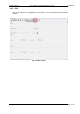
Click on Alarms button icon, highlighted in the nex figure, to access the alarms management
window.
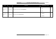
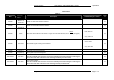
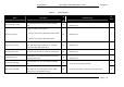
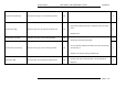
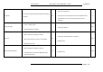
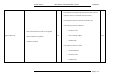
Fig. 28: Alarms window
The Alarm window allows the setting of alarm masks and the monitoring of alarms status.
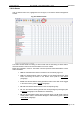
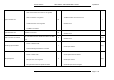
Use alarm masks to select how and which alarm have to be notified.
Masks are organized in columns. The sixteen columns represent sixteen destinations of each
alarm notification:
• GUI: the selected alarms status is notified on the Java alarm page icon.
• LCD: the selected alarms status is notified on LCD display lighting the alarm
button and listing the alarms in the Alarms menu (refer to LCD alarms
paragraph).
• Event: the selected alarms status generate an alarm event that will be logged
in the event memory (refer to Events
paragraph).
• R0…R3: the selected alarms switch on the corresponding relay.
• T0…T7: the selected alarms generate the corresponding trap messages (refer
to Network
paragraph to set destination IP addresses).
• RF: the selected alarms switch off the output RF signal. The RF mask is almost
entirely fixed in order to avoid board damages or malfunctioning (refer to RF Off
Alarms Mask paragraph).