
User's Manual Part 3

Screen Service SDT 501 UB-C ARK 1-T Operations
May, 2010 v 1.0 Page 3 - 160
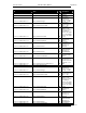
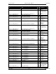
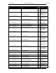
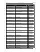
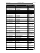
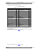
Each trap carries a 32 bits word in which each alarm represents one bit (0: Off, 1: On). The
following table shows the bit-to-alarm association.
Table 19.
Bit-to-trap association map
Alarm
Bit
Alarm
Bit
Up converter Osc. Unlock 0 Signal 10 MHz Lock 16
PS Voltage out range 1 Signal 120 MHz Lock 17
PS Current out of range 2 Signal 960 MHz Lock 18
Absolute Power Limiter 3 Input Not Valid Alarm 19
Up converter communication error 4 Late MIP Alarm 20
Temperature High Alarm 5 Network Delay Alarm 21
Temperature Level-3dB 6 Not Used 22
Temperature High Warning 7 File System Error 23
Forward Power High 8 Bad File in File system 24
Forward Power Low Warning 9 1PPS Lock 25
Forward Power Low Alarm 10 PPS Phase 26
Reflex Power High 11 System Delay 27
Fan Speed 12 DVB-T No MIP 28
Input Not Present Alarm 13 No Input 29
GPS Lock 14 FPGA Boot alarm 30
GPS Communication Error 15 Warm Up 31
E.g. A trap carrying the decimal value 805,306,368, corresponding to a binary value of
0011 0000 0000 0000 0000 0000 0000 0000, means that DVB-T No MIP (bit 28) and No
Input (bit 29) alarms rose.
The Community shown in trap messages can be set from Java interface in the Community
box within the Network window (refer to Network paragraph).
box within the Network window (refer to Network paragraph).