
Operator`s manual


TTM 57SL FOR SERATO SCRATCH LIVE • OPER ATOR’S MANUAL 1.9.2
8
GAIN
These “trim” controls adjust the
selected input to match other inputs.
These controls have a built-in Limiter
that prevents the signal from clipping
regardless of the Gain setting. If increasing the
Gain does not increase the signal level, then the
signal is already at maximum and the Limiter is
controlling the signal to prevent clipping. The
Gain range is +15 dB to off.
PAN
These controls pan the signal
between the Left and Right outputs.
HIGH / MID / LOW EQ
The control range is OFF to +6 dB.
These use 2nd-order, Linkwitz-
Riley, Accelerated Slope™ lters.
The Low-Mid cross-point is 300
Hz. The Mid-High cross-point is
4 kHz.
Kill switches provide instant-
off for each control. The skull
lights red and the band is off
when its Kill switch is pressed.
When the switch is released, the EQ goes back
to the setting of its EQ control. These switches
may be set to momentary or toggle operation
within the Scratch Live software. SEE “LATCH
KILL SWITCHES” ON PAGE 30.
FADERS
Magnetic faders are used for both
Channel Faders and Crossfader
(the same faders used in the
TTM 56S). Each fader has an
independent Contour control and a
Reverse switch.
CONTOUR
These controls provide a full
range of fader adjustment
from constant power (Slow) to
extremely fast cut (Fast).
REVERSE
These switches are provided for
each fader just to the right of each
Contour control. Reverse toggles on
(lit green) and off with each push of the switch.
These switches are slightly recessed to prevent
accidental engagement.
CHANNEL SWAP
This button reverses the
channel assignment for all three
faders. Pressing the switch
toggles Channel Swap on and off. When the
yellow indicator is lit, Channel Swap is engaged.
When channels are swapped, the PGM 1 Fader
controls PGM 2 and the PGM 2 Fader controls
PGM 1. PGM 1 is also moved from the A side of
the Crossfader to the B side of the Crossfader.
Fader Contour and Reverse controls stay with
the original Fader. Fader 1 Contour and Reverse
is always with the left Fader and Fader 2 Contour
and Reverse is always with the right Fader. This
switch is slightly recessed to prevent accidental
engagement.
METER
The Meter has two modes of operation. The
METER switch toggles between dual mono CUE
and STEREO HOUSE. When the green indicator
is lit, the Meter displays Stereo Mix, which is
being sent to all three outputs. When the green
indicator is off, the Meter displays Dual Mono
Cue, to show the levels of PGM 1 and PGM 2.
The red OL indicator lights at 0 dBFS (clipping).
The Meter displays loudness with a solid string
of lights, and how close you are to clipping with
a moving dot. If the red OL indicator lights, turn
the level down using the Gain control.
0
20
40
60
80
100
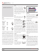
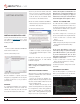
CHANNEL AND CROSSFADER CONTOUR
TRAVEL
DB ATTENUATION
SLOW
FAST
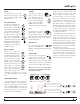
INPUT
Choose one of four INPUT sources for each
Program.
PGM 1 selects:
• Analog-1 (A1)
• Analog-2 (A2)
• Digital-1 (D1)
• Digital-2 (D2)
PGM 2 selects:
• Analog-3 (A3)
• Analog-4 (A4)
• Digital-1 (D1)
• Digital-2 (D2)
The Analog Inputs come from your turntables
or CD players. The Digital Inputs come from the
Virtual Decks in the Scratch Live software. If the
number for A1 or A2 is illuminated, the Input
has been selected by the Scratch Live software
as the control source input for Deck One. If the
number for A3 or A4 is illuminated, the Input has
been selected by Scratch Live as the control
source input for Deck Two. The backlit number
is a reminder that this source may be a control
signal and not audio. You may select a control
input and use it as a normal analog input at any
time without de-selecting it for control in Scratch
Live, but remember that if you are playing a
control record or CD, you will hear the control
signal. SEE “CONTROL SOURCE” ON PAGE 31.
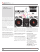
MIXER CONTROLS