TTM - OPERATOR’S MANUAL 1.8.1 LIVE • OPERATOR’S MANUAL 1.9.
TTM 57SL FOR SERATO SCRATCH LIVE • OPERATOR’S MANUAL 1.9.
Important Safety Instructions Introduction 1. Read these instructions. 2. Keep these instructions. 3. Heed all warnings. 4. Follow all instructions. 5. Do not use this apparatus near water. 6. Clean only with a dry cloth. 7. Do not block any ventilation openings. Install in accordance with manufacturer’s instructions. 8. Do not install near any heat sources such as radiators, registers, stoves, or other apparatus (including amplifiers) that produce heat. 9.
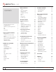
Mixer Controls Contents 8 Playback Control 15 Aux In 9 The Control Record 15 Mic Level and EQ 9 The Control CD 15 Output Levels 9 Vinyl Scroll 15 Headphone Cueing 9 Phones 9 Cue 9 Virtual Deck 16 Master Cue 9 Visual Aids 16 FlexFX Loop 9 Tempo Matching Display 16 Main Screen Overview 16 Track Overview Display 16 Getting started 10 Main Waveform Display 16 Installing Scratch Live 10 Beat Matching Display 16 Mac 10 Master Gain 17 Windows 10 33 / 45 Speeds
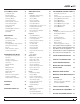
22 Additional Setup 30 Loading the SP-6 22 Hardware 30 Controlling Scratch Live Playing Samples 22 USB Buffer Size (Latency) 30 Groups 34 SP-6 Instant Doubles 22 Updating Firmware 30 Customizing Control Assignments 34 SP-6 Play Modes 22 Save to Mixer 30 (Group B1) General Controls 35 SP-6 Pitch Controls 23 Phono Sensitivity 30 (Group B2) Library 35 SP-6 ‘Play from’ Selector 23 Transform Direction 30 (Group B3) Playback 35 SP-6 Track Overviews 23 Latch Kill Switches 3
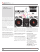
TTM 57SL Mixer Overview USB DUAL CD PLAYER OUTS TURNTABLE OUT GROUND GROUND TURNTABLE OUT The TTM 57SL Performance Mixer combines the best technologies that Rane and Serato have to PGM 1 PGM 2 2 1 D offer in a single high-performance mixer. The TTM 4 6 0 10 2 2 1 D A -15 INPUT R +12 FlexFX MIC HIGH 8 10 OL OFF +6 6 0 10 8 BOOTH 4 6 0 10 2 +6 8 AUX OUT +6 P2 MIC LEVEL range of possibilities for your performance.
USB Streaming Audio Mic Input The Mic Input will accept either a Connecting the Mixer MIC There are eight channels balanced ¼˝ TRS (tip-ring sleeve) of plug or an unbalanced TS (tip-sleeve) the USB port. Two stereo streaming audio over plug. Any type of microphone may channels from the computer be used, except those that require and two stereo channels to phantom power to operate. See “Mic the computer. While internal processing is all 24- Level and EQ” on page 9. bit 44.
Mixer Controls These “trim” controls adjust the selected input to match other inputs. These controls have a built-in Limiter that prevents the signal from clipping regardless of the Gain setting. If increasing the Gain does not increase the signal level, then the CHANNEL AND CROSSFADER CONTOUR TRAVEL DB ATTENUATION Gain 0 20 SLOW FAST 40 60 80 100 signal is already at maximum and the Limiter is controlling the signal to prevent clipping. The Gain range is +15 dB to off.
Aux In Phones FlexFX switches are provided for PGM 1 and This level adjusts the level of the The headphone output can PGM 2. Pressing the FlexFX switch lights Auxiliary Input signal. This is a full- deliver very high volume to the green indicator and sends the signal to HEADPHONES the external FlexFX Loop. Press the switch range control providing Off to +6 dB some headphones. To avoid gain adjustment.
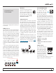
Getting Started 1. Connect your TTM 57SL with the USB cable TIP: The driver updater can install drivers for before you insert your installation CD. When different types of Scratch Live hardware, not you first connect it, Windows will attempt to just the SL 3. For example, if you play at a install the drivers via the hardware wizard. club that uses an SL1, just connect the mixer Cancel and close the hardware wizard. and run through the driver updater as above. 2.
TROUBLESHOOT: The TTM 57SL mixer is not Connecting a TTM 57SL 4. Select Scratch Live as the audio source for recognized. It takes five seconds for Scratch the mixer by turning the input selector knobs Live to detect the TTM 57SL. The mixer can be on the top of the TTM 57SL to D1 and D2 on unplugged at any time; you do not need to exit the PGM1 and PGM2 channels respectively. Scratch Live before disconnecting the hardware.
How to Calibrate Scratch Live Calibrating Scratch Live For optimal performance the inner ring should With music playing in the background (from be as close to circular as possible. Use the any source), put your needle on record with the scope zoom slider (1x to 16x) to zoom in or out turntable stopped. If you are using CD players, as necessary. Use the scope L/R balance and the same rules apply. Have the CD deck paused P/A balance controls to adjust the shape of the or stopped while calibrating.
2. Once you have located your music, drag the Importing and Playing Music Playing Music folder or files you want to import onto the Click on the All… icon to show all the tracks in purple “All...” icon. This is located to the left of your library. Use the keyboard shortcut Shift + your screen at the top of the crates and playlist Left Arrow to load the highlighted track on to window.
Set Auto-BPM Whitelabel.net Preparing Your Files If this option is checked while analyzing files, Scratch Live will calculate the estimated tempos of your files. If Scratch Live is confident that the auto-BPM estimate for a file is accurate, it will be written to an ID3 tag* in the file. The auto-BPM function will not be applied if the track already contains BPM information.
Vinyl Scroll File Management Playback Control Vinyl Scroll allows you to select and load tracks using only your turntables (or CD player) – no contact with the computer necessary! To use Vinyl Scroll with turntables, lift the needle off the record and drop it into special “bonus track” section at the end of the record’s A side. The movement of the control disk now controls the selected track within your library.
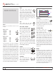
Tempo Matching Display Main Waveform Display This view provides a close-up Main Screen Overview of the track, including color coding to show the frequency The Tempo Matching display area provides a of the sound; red representing helpful tool for beat matching.
1. Start the track playing on the right deck. After a few seconds, blue peaks appear in the Tempo Matching display. Censor Tap Tempo For tracks with no BPM information, Use the censor button to ‘mask’ parts there of a song, or use as a special effect. is a tap tempo button displayed where the BPM usually When you press the censor button, the track is, in the song info area. Pressing alt-space bar starts playing backwards from that point.
USB Dropout Indicator The USB dropout indicator on the main screen is a useful trouble shooting internal mode will activate after 1 second. Use the keyboard shortcut F1 (left deck) or F6 (right Scratch Live Modes deck) to switch to absolute mode. NOTE: Be careful when scratching near the tool if you have problems with audio dropouts.
Internal Mode Bend down - Create a temporary More Controls decrease in the playback speed. Use You can also control playback using the bend down if the two tracks are in time, but this computer keyboard shortcuts — turn Caps Lock track is slightly ahead of the other track. on to enable. See “Playback Keys Use Shift” on page 31. Bend up – Create a temporary increase in the playback speed.
TIP: Zoom in on the waveform using the – and Cue Points + keys and ‘scrub’ to the desired position for greater accuracy when setting cue points. Looping Enable Hot Cues To turn on hot cues, check “enable hot cues” in the playback tab on the setup screen. When hot cues are enabled, you can set cue points simply by pressing the number keys 1 through 0 (no ctrl modifier required). Note that you can only add cues this way if the cue point slots are empty. See “Enable Hot Cues” on page 20.
off, disable the adjust loops with vinyl option The A - Slot Loop Roll with MIDI in the setup screen. There are 9 available loop A special loop slot ‘A’ exists for auto-looping. The You can assign loop roll to MIDI in several ways: slots per track. If a loop is set in a given slot, act of using the auto-loop buttons sets a loop in After pressing the MIDI assign button in Scratch the background (behind the loop number) will be the ‘A’ slot, following the rules above.
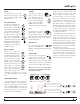
SP-6 Sample Player The SP-6 Sample Player allows you to play up to six sources of audio, in addition to the tracks playing on the Virtual Decks. Any audio file in your Scratch Live library can be loaded to any one of the six slots, allowing playback of short samples, sound effects, or full length tracks. The SP-6 is enabled when the TTM 57SL is plugged in, but not operational in the offline player mode. Click on the sample player button to access the SP-6 window.
SP-6 Pitch Controls SP-6 Slot Volumes you to choose the L, M, R output for each slot. There are individual Each individual These output routings will be saved when you Pitch Slider, Bend, sample slot has a close down Scratch Live, so the next time you Nudge, and Keylock controls for each sample separate volume slider and gain control. launch Scratch Live, your preferred settings will remain the same. slot. The BPM is also displayed next to the pitch slider.
Presets Assigning Controls To enable MIDI assign mode, click MIDI Control the MIDI button. Hovering the mouse pointer over a control will bring up the MIDI assignment box, showing the current assignment status. To assign a MIDI control, click on the control in Scratch Live, then move the MIDI control. The MIDI assignment box should update to show it MIDI presets are accessible in the MIDI panel of has mapped the controls to one- another. the setup screen.
TIP: Check the protect library option in the Organizing Your Music Using the Song Browser setup screen to prevent changes to your crates. If you do delete a crate by accident, you can get it back from the recycle bin / trash. Crate files have the extension .crate. Subcrates You can drag and drop crates into other crates to make subcrates.
TIP: Select the contents of the prepare Start Session / End Session - To start or end a window and drag them onto the new crate session, click the corresponding button. button (+) to save your selection as a crate. You can choose to show tracks which you have auditioned, but not actually played, by checking the show “unplayed tracks” box. The session will then also list these tracks in grey, History along with actual played tracks.
Display Album Art Scratch Live Backup Scratch Live stores your library database and crates information in the Scratch Live folder Recording on your hard disk. This folder is created on a drive when files are added to Scratch Live. A copy of each Scratch Live folder called ScratchLIVEBackup is created next to the folder it is backing up. This folder is created when MP3 files can contain album art information. exiting Scratch Live.
(thus avoiding periods of silence). You can set Recordings can be loaded onto the decks, renamed, and managed like other files. Recordings are saved in “MyDocuments\My- the gate level by clicking the dropdown menu in LiveFeed the LiveFeed filename. The lower the gain setting the more sensitive the gate is. Music\ScratchLive\Recording” on a PC and “~/ Music/ScratchLive/Recording Temp” on a Mac. The amount of time available to record is Recordings are saved as 16-bit, 44.
KEY ctrl - L Keyboard Shortcuts These actions can be accessed directly from the computer keyboard. NOTE: Playback, cue and speed controls use Shift or Caps Lock, you can turn this off in the setup screen. See “Playback Keys Use Shift” on page 31.
Additional Setup Updating Firmware Save to Mixer If a firmware update is available after installing Click these buttons to transfer settings to a new Scratch Live software release, an update the mixer. The save to mixer buttons in the firmware button appears in the setup screen. Effects sections save to the mixer processors The firmware upgrade takes approximately 10 independently so it can be used without Scratch seconds, during which time the mixer will not be Live running and attached.
Playback Meters Use Auto Gain This button switches the meter mode, which is Auto gain enables you to set a uniform volume reflected by the mixer hardware. level for the tracks in your library. When a track is in auto gain mode, the track gain knob appears Phones depressed. To enable auto gain, check the “use auto This button changes the state of the Master Cue gain” box under the playback tab. Provided you button on the mixer.
Hi-Fi Resampler Vinyl Control Drop to Absolute Position This significantly reduces digital distortion at very This detects a deliberate repositioning of the slow or very fast record speeds, increasing the needle, and moves the playhead to the absolute CPU load slightly. This option is off by default, position of the needle, as in absolute mode. the old resampler is used when switched off. Accidental skipping of the needle does not reposition the playhead.
Library Protect library Import AAC Files Uncheck this setting to remove files and crates Turn this option off if you do not wish to import from your library. Enable to lock your library and AAC files into your library. Changing this option prevent accidental file or crate deletion while will cause your iTunes library to be reloaded if using Scratch Live. Enabling this setting will also you have the ‘read iTunes library’ option turned lock all file tags and crate names, so that no text on.
When the LED next to J1 or J2 is on, the joystick Customizing Control Assignments controls Scratch Live software. When the LED is You can customize almost all of the software not lit, the joystick acts as a transform switch. To control assignments. To change what a button, switch between using the joystick as a control parameter knob or joystick does to Scratch Live, for Scratch Live and a transform switch, press right-click on the control label.
(Group B1) General Controls (Custom Group 1) This is the first group shown below with default commands when you first start Scratch Live. These give you basic playback controls and up to three cue points per Virtual Deck. The orange arrows (left) control the left Virtual Deck and the blue (right) arrows control the right Virtual Deck. The joysticks default to transform mode (LEDs off). Press the joystick in (LED on) to activate its Push to load track on left Deck.
(Group B4) Cueing & Looping Turn to adjust, and push to set loop in point. Turn to adjust, and push to set loop out point. To access this group, press the GROUP button on the mixer, then press B4. This group gives you access to all the cue points and looping functions. To select which of the Virtual Decks a given effect is applied to, press the mixer’s DECK button. The LED next to the button Hold the joystick up or down and press a B button to set a cue point. Next loop.
Effects Internal Digital Effects TTM 57SL ships with Echo in Processor 1, and There are two Effects Processors available in the LP Filter in Processor 2 before Scratch Live TTM 57SL. Digital Effects hang out in the mixer reassigns them. instead of the software so they are available for signal processing even when Scratch Live is not running. Each processor can load one of ten effects: NOTE: These defaults can be changed and saved to the mixer. See “Save to Mixer” on page 30.
Control Assignment Summary Basic Effects Controls The selected effect is edited with the remaining Footswitch soft controls. The function of some controls The last soft control is the optional foot-switch. depends on the selected Effect. Specific control A footswitch allows hands-free control of these P1 controls the design frequency. functions are detailed for each Effect.
Sweep Filter Control Assignments HP Filter is an automatically sweepable High Pass Filter, with the following response: 31.5 Hz FREQUENCY RESONANCE TAP BPM DEPTH P1 1 MULTIPLIER 3/4 1 2 1/2 1/4 J1 B1 GROUP B3 B4 INSERT POINT 8 PGM 1 min 0.7 • P2 Depth min PROCESSOR 2 B2 4 16 • P2 Resonance 2 PROCESSOR 1 PGM 2 AUX B MAIN B5 B6 CUE EFFECT ON ON 16 kHz max 3.
P2 Resonance / Depth Resonance is adjusted using the primary function of P2 (indicator off). The diagrams show the different resonances for each Filter type. Phaser / Flanger Control Assignments PHASER FREQ or FLANGER DELAY FEEDBACK TAP BPM DEPTH LP and HP Filter Resonance determines how peaked the cutoff is, which is adjustable over a range of 0.7 to 3.0. P1 BP Filter Resonance determines the width of P2 the peak, which is adjustable over a range of 0.7 to 3.0.
P1 Phaser Frequency / Flanger Delay / Tap BPM Echo Effects Control Assignments The Phaser’s primary function of P1 (indicator off) is filter design frequency, which starts at 722 DELAY FEEDBACK TAP BPM HP ECHO FREQ Hz and is adjustable from 31.5 Hz to 16 kHz (9 octaves). The full sweep of the filter is reached in 11/3 rotations of P1. P1 The Flanger’s primary function of P1 (indicator P2 off) is Base Delay, adjustable from 0 to 11.6 milliseconds.
P1 Delay / Tap BPM Once you turn P1, the lock icon disappears, the Hold Echo Effects Control Assignments Multiplier number turns white and P1 becomes a Delay control. Delay has a range of 1ms to DELAY FEEDBACK TAP BPM HP ECHO FREQ 2.9 seconds, and a track without a BPM tag will start at 500 ms. A slow turn gives 1ms adjustment resolution, while a fast turn increases P1 the resolution to 200 ms per step.
P1 Delay / Tap BPM Once you turn P1, the lock icon disappears, the Desecrator Control Assignments Multiplier number turns white and P1 becomes a Delay control. Delay has a range of 1ms to DRIVE LEVEL SAMPLE RATE TAP BPM BIT DEPTH 2.9 seconds, and a track without a BPM tag will start at 500 ms. A slow turn gives 1ms adjustment resolution, while a fast turn increases P1 the resolution to 200 ms per step.
I can’t get the Scope View to show nice clean circles Troubleshooting and Frequently Asked Questions Select phono as the audio input level in the setup screen if you are using vinyl. Check your needles and make sure they are clean. If the circles look fuzzy, try cleaning your control record. If the Scope View shows a line instead of a circle, Scratch Live is only receiving a signal from one channel — check all your cables, and the connection between your cartridges and the tone arm.
Corrupt File Descriptions and Diagnoses Corrupt file: This MP3 contains invalid frames. This MP3 contains frames which do not conform strictly to the official MP3 specification. Scratch Live can not be certain that this file will play back 100% accurately. Corrupt file: This file contains corrupt frames that may result in audible glitches. This file contains two or more contiguous corrupt frames. Since corrupt frames are replaced with silence, this could result in what might sound like an audio glitch.
Scope Reading and Fixes Most of the problems that occur with Scratch Live can be attributed to it not getting a good reading of the control signal from your records or CDs. These examples show what the scopes on the setup screen can look like to help solve possible problems. Some problems cause similar looking scopes, e.g., if your scopes look like the Dusty Needle one, the cause could be a damaged needle. GOOD SIGNAL - Clean signal with 100% tracking.
RECORD BURN - This section of the control vinyl has LEFT CHANNEL MISSING - The signal from the needle RIGHT CHANNEL MISSING - The signal from the been worn. Swap sides or use the track start offset. is not reaching the TTM 57SL Check the cable and needle is not reaching the TTM 57SL. Check the cable cartridge connections. and cartridge connections.
Mixing With One Turntable or CD Player This single turntable technique allows you to mix as if you had two turntables, using just one. If one of your turntables is not performing properly, or if you only have one available, you will be able to continue to mix the way you are used to. The following is a step-by-step description of how to do perform a mix using only your right turntable or CDJ with the instant doubles feature. Menu Settings Magnetic Fader Q and A Q.
water. Make sure the part is clean and dry 8. NOTE: In order to achieve the highest possible Magnetic Fader Rail Cleaning before lubricating or reinstalling. accuracy, each magnetic fader is factory calibrated for the location in which it was 11. Removal of grease or other stubborn debris shipped. If you remove the faders for cleaning, may require alcohol or contact cleaner. Make make sure you mark them. This helps you to sure the part is clean and dry before lubricating or reinstalling.
Analog Diagram Simplified block diagram of the analog inputs around the DSP. Only one channel is shown.
Footswitch Diagram Rane does not manufacture or distribute the optional foot switch. The foot switch needs to be a passive pull-down device capable of TTM 57SL Specifications grounding the TIP, RING or TIP and RING to get the three possible states. Good choices are the DigiTech FS300 or GNXFC. To the right is a basic diagram of a 3-switch foot switch. Three buttons gives the most flexibility, but you can also use one or two button footswitches.
Declaration of Conformity Standard(s) to which conformity is declared: Application of Council directive: EN60065:Ed. 7.
Factory Authorized Service Your unit may someday need to be serviced by the Rane Factory if you live in the USA. International customers should contact your dealer or distributor for service. You must call the Rane factory before shipping. Please do not return your unit to Rane without prior authorization. Rane Corporation To obtain service or a Return Authorization in the USA, please phone 425-355-6000 or Fax 425-347-7757 Limited U.S.A.
Warranty Procedure - Valid in U.S.A. only NOTICE! You must complete and return the warranty card or register your product online to extend the Warranty from 2 years to 3 years! TO VALIDATE YOUR EXTENDED WARRANTY: Use the postcard that came in the box with your unit, or go to www.rane.com and click on New Product Registration. Fill out the warranty completely, being sure to include the model and serial number of the unit since this is how warranties are tracked. If your Rane product was purchased in the U.S.