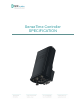
SenseTime Controller SPECIFICATION
©Copyright SCR Engineers LTD. 2016 This SenseTime Controller Specification is copyrighted. All rights are reserved and no part of this publication may be reproduced or transmitted in any form or by any means without prior written consent. Disclaimer The information in this manual was accurate and reliable at the time of its release. However, we reserve the right to change the specifications of the product described in this manual without notice at any time.
SenseTime Controller Contains FCC ID: AMUBUM Manufacturer: SCR Engineers Ltd. This device complies with Part 15 of the FCC Rules. Operation is subject to the following two conditions: (1) this device may not cause harmful interference, and (2) this device must accept any interference received, including interference that may cause undesired operation.
1 2 System Overview (SenseTime Controller – Tag) ...................................................................................... 1 Part 2: Technical Specifications ................................................................................................................ 2 2.1 2.2 2.3 2.4 SenseTime Controller Block Diagram ............................................................................................... 2 SenseTime Controller RF Parameters ........................................
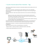
1 System Overview (SenseTime Controller – Tag) The Cow Tag* enables farmers to monitor the cow health condition and the readiness of the cow for insemination. The SenseTime Controller is connected to the main computer or server in the cowshed by Ethernet connection and transfer messages between the computer and the cow tags using RF communication.
SenseTime_Controller Specification V0 07 Page 2
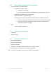
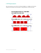
2.2 SenseTime Controller RF Parameters Two RF Modules FCC ID: AMUBUM o RF Frequency Tx/Rx: 2.4GHz IEEE 802.15.4 standard Channels 11(2.405 GHz) to 26(2.480 GHz) for a total of 16 RF Channels. o Baud Rate: 250K Bit/Sec (Not configurable) o Output RF Power: 10mW Maximum o Internal Antenna type: Internal diversity patch antenna, ~10dBi, directional Contains vertical and Horizontal antennas, RF transmitting done ALWAYS only via one antenna, as default via Vertical antenna.
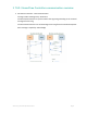
3 TAG / SenseTime Controller communication overview SenseTime Controller – TAG communication The tag initiates message every 20 minutes The SenseTime Controller is synchronized to the tag timing according to the received messages from the tag The SenseTime Controller can send messages to the tag from the cowshed computer.
4 RF Requirements Wi Fi system working in the same area according to IEEE802.11 or IEEE802.15.4 (see below) should not have a frequency that overlaps the working frequency band of the system.
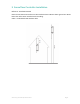
5 SenseTime Controller Installation Reference: Installation Manual Note: The SenseTime Controller must be installed at least 3 Meters above ground or 1 Meter below the rafters when installed inside a building.
6 Operational and Environmental Conditions Operation and Storage -30⁰C to +50 ⁰C 0-95% Relative Humidity IP standard complies to IP65 Complies with ETS 300 019 -2-2 T2.3 Complies with ETS 300 019 -2-1 T 1.2 Transportation 7 Radio, EMC, POE and Safety Radio Number Market Standard EN 300 440 1 Europe 2 USA/Canada 47CFR PART 15, Sub C, sec 15.
Appendix A - Product Data Product name SenseTime Controller CLT00xxx Product Catalog # Rating xxx – optional marketing part numbers as specific PN for specific customer or optional interfaces. 40-57VDC (48V Nominal) 0.1A from LPS POE according to IEEE802.3at Or (Optional) 24VDC±10% from LPS Color TBD s/w version TBD Product mechanical dimensions Length: 250mm Width: 1815mm Height: 114mm Wight: ~1.