
Manual

User’s Manual
Scott Edwards Electronics, Inc.
1939 S. Frontage Road, Suite F, Sierra Vista, AZ 85635 USA
ph: 520-459-4802 • fax: 520-459-0623 • www.seetron.com
BPP-420 • v4.0 • 2/03 • pg 3
Basic Operation
Set the configuration and connect serial input/power to the BPP-420 as shown in the previous sections.
Now you can send text serially to the display. On a PC, you may use a terminal program (such as the
Windows Terminal or Hyperterminal accessory, or Procomm for DOS). Set it for the appropriate baud
rate (matching switch 2). In addition to the baud rate, the terminal should be set for:
no parity 8 data bits 1 stop bit flow control = none local echo = on
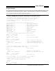
Piezo Buzzer “Bell”
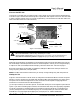
As figure 1 shows, you can connect a piezo buzzer to the BPP-420. The buzzer will beep when the
ASCII bell character (cntl-G) is received. The buzzer must have an internal oscillator and work on
5V at 25mA or less. Suitable units are Jameco 76021, Radio Shack 273-065, and Digi-Key P9948.
Connecting anything other than a suitable buzzer to J4 will void the warranty.
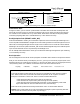
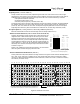
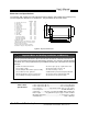
Figure 2. Connecting to PC serial port, BASIC Stamps.
PC Serial (comm) Port
DB-9 female
(solder side)
1 2 3 4 5
6 7 8 9
SER
GND
+5
+5
power
supply
BASIC Stamps
Stamp
GND (Vss)
+5V (Vdd)
I/O pin 0
J1
GND
+5
SER
OLD-MODE Operation
The codes and features described in this manual are available only when switch 1 (mode) is
OFF. When mode is ON, the interface emulates the operation of our original LCD Serial
Backpack
®
installed to a 4x20 LCD. There are some inevitable differences:
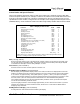
• BPP-420 draws about 5mA versus 2mA for the older unit.
• BPP-420 does not require a delay after clearing the screen (buffer).
• BPP-420 controls the LED backlight, even when in old-compatibility mode. Send
bytes <254><255> for ON and <254><0> for OFF (old mode only).
New users of this product should always leave switch 1 OFF to use the newer features.
NOTE: Users of older 4x20 serial LCDs connected the backlight to power separately. DO NOT
do that with this version! Connect power only through J1.
J1
Backlight Option Pads (BRIGHT and BL_ON)
Pads marked BRIGHT and BL_ON customize the operation of the LED backlight. Soldering a wire
across the pads marked BRIGHT changes the current-limiting resistance in the backlight circuit from
16Ω to 8Ω, increasing the brightness of the light. This increases max current draw to about 150mA.
Soldering a wire across the pads marked BL_ON connects the backlight directly to the module’s power
input so that whenever the unit is powered up the backlight is on.
Do not attempt these modifications unless you are skilled at soldering. Damage due to poor soldering
is not covered by warranty.