
Manual

User’s Manual
Scott Edwards Electronics, Inc.
1939 S. Frontage Road, Suite F, Sierra Vista, AZ 85635 USA
ph: 520-459-4802 • fax: 520-459-0623 • www.seetron.com
BPP-420 • v4.0 • 2/03 • pg 2
Pinout of the BPP-420
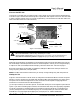
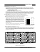
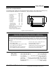
Connections to the BPP-420 are made through a 5-pin header on the serial interface daughterboard,
as shown in figure 1 below. Note that the photo is upside down with respect to the LCD. This was done
in order to show the labels on the circuit board rightside-up. (The same board is used with 4x40 LCDs,
where the labels match the LCD orientation.)
back
Figure 1. Connections and controls.
Configuration
Mode. Set the mode switch (1) OFF/down to use the features and instructions described in this manual.
Set mode ON/up to emulate operation of the LCD Serial Backpack
®
. Unless you are using this display
to replace an older (circa 1996) 4x20 serial display, leave this switch OFF. See note on page 3.
Baud. Set baud switch (2) OFF/down for 2400 baud, ON/up for 9600 baud. Other parameters are
always no parity, 8 data bits, 1 stop bit (N81).
NOTE: The BPP-420 reads the switches only at startup. Change settings only with the power off.
Hookup for Use
Figures 1 and 2 show how to connect serial I/O and power to the BPP-420. Make sure that the power
polarity is correct. Reversing +5 and GND will damage the BPP-420 and possibly your power supply.
The power source should be regulated to 5 volts ±0.25 volts and be capable of supplying 100mA
(maximum current draw with the LED backlight on).
J1, the 5-pin connector, has two extra pins for +5 and GND. These pins are arranged in a pallindrome
layout. If you make a matching 5-pin connector, the connections will always line up properly regardless
of connector orientation. Suitable female crimp sockets for making connectors are available from
Jameco (www.jameco.com, PN: 100765). Digi-Key carries ready-made 5-pin socket and flex-cable
assemblies in varying lengths (www.digikey.com; example part no.: A9BAG-0506F-ND).
Closeup of J1
TOP
pins are 0.025" posts
on 0.100" centers
contrast
control
darker
Closeup of S1
1 = MODE
2 = BAUD
NORMAL
2400
OLD
9600
OFF ON
+5V
Serial data
GND
Duplicate +5V and GND
connections (see text)
Closeup of J4
piezo-buzzer output:
5Vdc at 25mA or less
Do not reverse +5V and GND, even momentarily. Reversed power will destroy the electronics.
Do not exceed 5.5V into +5. Overvoltage will damage the module.
Connect power only through J1. Connecting power to other points on the module will damage it.
Read and follow installation guidelines on page 10. Improper handling voids the warranty.