
Manual

User’s Manual
Scott Edwards Electronics, Inc.
1939 S. Frontage Road, Suite F, Sierra Vista, AZ 85635 USA
ph: 520-459-4802 • fax: 520-459-0623 • www.seetron.com
BPI-216 • v1.2 • 07/00 • pg 3
Basic Operation
Once the BPI-216 is properly connected and configured to match the baud rate of the computer/program
that will be talking to it serially, data sent to it will appear on the display. For example, if you send
“Hello” then “Hello” appears on the display. The cursor (printing position) automatically moves from
left to right.
You can also send instructions to the BPI-216. To identify a particular byte as an instruction, precede
it with the instruction prefix character, ASCII 254 (0FE hex, 11111110 binary). The interface treats the
byte immediately after the prefix as an instruction, then automatically returns to data mode.
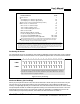
Example: The clear-screen instruction is ASCII 1. To clear the screen, send <254><1> (where the <>
symbols mean single bytes set to these values, not text as typed from the keyboard). Table 1 lists the
LCD instructions.
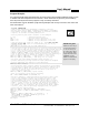
Startup Time
When the BPI-216 is first powered up, it requires about 750 milliseconds (ms) to initialize the LCD
and get ready to receive data. Programs should wait about a second after powerup before sending data
to the BPI-216.
Hookup for Use
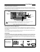
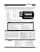
Figure 3 shows how to connect the BPI-216 to PCs and BASIC Stamp computers in order to run the
example programs presented later in this manual. Refer to figure 1 or the markings on the interface
for the locations of +5, GND and SER(ial in).
The 5-pin connector has two extra pins for +5 and GND. These pins are arranged in a pallindrome
layout. If you make a matching 5-pin connector, the connections will always line up properly regardless
of connector orientation. Ready-made wiring harnesses and instructions for making your own hookups
are available from www.seetron.com. If you do not need a removable connector, you may wire-wrap or
solder wires directly to the header posts.
Figure 3. Connecting to PC serial port, BASIC Stamps.
PC Serial (comm) Port
DB-9 female
(solder side)
1 2 3 4 5
6 7 8 9
SER
GND
+5
+5
power
supply
BASIC Stamps
Stamp
GND (Vss)
+5V (Vdd)
I/O pin 0 (P0)
BPI-216
GND
+5
SER
BPI-216
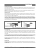
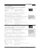
Setting the Baud Rate
Set the BPS switch down for 2400 baud; up for 9600. At either rate, the serial characteristics are no
parity, 8 data bits, 1 stop bit. For more information on serial transmission, see the application note:
www.seetron.com/ser_an1.htm.
NOTE: The interface reads the BPS switch only at startup. Change the BPS setting only with the
power off. The Backlight (BL) may be turned on or off at any time.
Note: the gray lines are loopback connections that may
be required if the PC software/hardware expects
handshaking. They may be omitted in most cases.