
Service manual


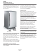
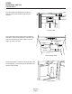

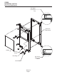
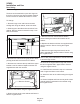

Table Of Contents
- Table of Contents
- Product Description: Page 2
- Cabinet Dimensions Page 3
- Location Recommendations: Page 4
- Familiarization Page 5
- Decorating Features: Page 6
- Door Panel Attachment Page 7
- Door Swing Page 8
- Plumbing - Pump Model Page 9
- Plumbing: Gravity Drain Model Page 10
- Electrical and Start Up Page 11
- Use Page 12
- Maintenance Page 13
- How to remove scale from the ice making system. Page 14
- Service Table of Contents
- SCN60 service Page 1
- Components: Page 2
- Evaporator and Auger Page 3
- Control System Page 4
- Water System Page 5
- Storage Page 6
- Performance and Technical Specs Page 7
- Electrical Sequence Page 8
- Service Diagnosis Page 9
- Service Diagnosis Page 10
- Component Diagnostics Page 11
- Ice Capacity Page 12
- Removal and Replacement Page 13
- SCN60 Gearbox Access & Removal Page 14
- Water Seal Replacement Page 16
- Evaporator Replacement Page 18
- Drain Pump (if equipped) Page 19
- Compressor replacement. Page 20
- Bin and Cabinet Page 21
- Table of Contents
Familiarization
The control panel is visible when the door is
opened. It has three indicator lights and two
switches.
The model and serial number plate is located on
the bottom of the control panel box. The Bin Light
and Ice Level Sensor are also visible from that
angle, as is the Ice Chute.
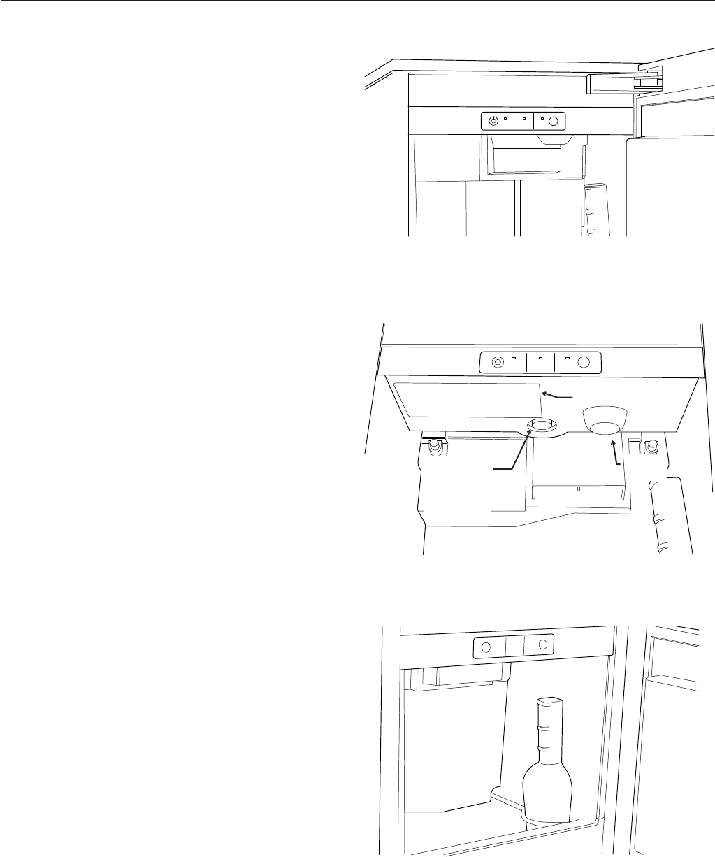
The Scoop Holder is located on the right side of the
ice storage bin. The normal ice level is about level
with the scoop holder.
May 2011
Page 5
SCN60
Installation and Use
Ice
Making
Check
Water
Time to
Clean
Clean
Reset
Control Panel
Scoop Holder
Ice
Making
Check
Water
Time to
Clean
Clean
Reset
Serial Number Plate
Light
Ice Level
Control
Sensor
Serial Plate