NM952 INTRODUCTION To the owner or user: The service manual you are reading is intended to provide you, and the maintenance or service technician, with the information needed to install, start up, clean, maintain, and service this ice system. The NM952 is a modular ice system that fits a variety of Scotsman ice storage bins.
NM952 FOR THE INSTALLER BACK VIEW: AIR COOLED BACK VIEW: WATER COOLED Note: Allow 6" behind and 6" above either unit for air circulation, utility connections, and service. ELECTRICAL INLET ELECTRICAL INLET WATER INLET 9.5" 5.25" 5.25" 7.3" 3" 3" Condenser Inlet 3/8" FPT WATER INLET 3/8" FLARE 2.9" 2.1" Condenser Drain 1/2" FPT 3.4" 5.7" DRAIN 3/4" FPT DRAIN 3/4" FPT 4.9" 7.
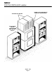
NM952 FOR THE INSTALLER Typical Storage Bin with Extension and Bin Top Location: After uncrating and inspection, the unit is ready for installation. It is important that the machine be installed in a location where it has enough space around it to be accessible for service, and minimum of 6" be allowed at the back for air circulation on air cooled models. Try to avoid hot, dirty and crowded locations. Be sure that the location for the machine is within the environmental limitations.
NM952 FOR THE INSTALLER: Location DO NOT STACK ANYTHING IN FRONT OF THE MACHINE(S) TWO UNITS ON ONE BIN ALLOW ROOM FOR AIR CIRCULATION AND SERVICE ACCESS August 1993 Page 4
NM952 FOR THE PLUMBER CONFORM TO ALL APPLICABLE CODES water pressure to all lines must always be above 20 psig, and below 80 psig. Water Inlet Air Cooled Models: The recommended water supply is clean, cold water. Use 3/8" O.D. copper tubing, connect to the 3/8" male flare at the back of the cabinet. Install a hand valve near the machine to control the water supply. Water Treatment: In most areas, a water filter of some type will be useful.
NM952 FOR THE ELECTRICIAN CONFORM TO ALL APPLICABLE CODES The electrical power to the unit is supplied through the junction box at the rear of the machine. Check the nameplate (located on the back panel) for the voltage requirements, and for the minimum circuit ampacity. The machine requires a solid chassis to earth ground wire. The ice maker should be connected to its own electrical circuit so it would be individually fused.
NM952 FOR THE INSTALLER Final Check List 1. Is the ice system installed indoors in a location where the air and water temperatures are controlled, and where they do not exceed the design limitations? 5. Is there a minimum of 6" clearance at the back of the machine for proper service access and air circulation? 6. Is the water pressure a minimum of 20 psig? 2.
NM952 START UP Pre-Start Inspection 1. Remove the front and side service panels. 2. Check that the styrofoam shipping blocks have been removed. 3. Inspect the interior of the machine for loose screws or wires. Check that no refrigerant lines are rubbing each other. Check that the fan blade turns freely (air cooled). 4. Check that the unit is installed correctly according to the final check list (page 7). Start Up 1. Go through the prestart inspection. 2.
NM952 COMPONENT DESCRIPTION Control Box: Contains the electrical controls that operate the machine. High Pressure Cut Out Switch: A manual reset switch sensing the high side refrigeration pressure. It is set to shut the machine off if the discharge pressure should ever exceed 400 psig. Evaporator: A vertical stainless steel tube, refrigerated, and water filled. In it there is a stainless steel auger. Compressor: The refrigerant vapor pump.
NM952 COMPONENT DESCRIPTION: Control Box Contactor: A definite purpose contactor connecting the compressor and the remote condenser fan motor to the power supply. Circuit Board: Controlling the ice machine through sensors and relays. The sensors are for ice level and water level. The relays are for the gear motor (with a built in time delay to clear the evaporator of ice when the unit turns off) and for the compressor. Transformer: Supplies low voltage to the circuit board.
NM952 COMPONENT DESCRIPTION Evaporator: A refrigerated vertical tube filled with water and containing a water seal and auger. Auger: A solid stainless steel double spiral auger, it pushes the ice crystals up to the top of the evaporator. Water Seal: A two part "face" seal, the top half rotating with the auger, the bottom half stationary, the sealing action being where the two seal "faces" meet. Ice Sweep: A plastic cap with "fingers". It revolves with the auger to "sweep" the ice into the ice chute.
NM952 ELECTRICAL SEQUENCE Refer the wiring diagram as needed. If the machine is switched off at the master switch, but is otherwise ready to go, switching the master switch to on does the following: • The bin empty light on the circuit board goes on • There is a 15 second delay • If there is enough water in the reservoir, the more minutes, clearing out ice in the evaporator, and then • The auger motor relay opens, and the auger circuit board will allow the machine to start up.
NM952 OPERATION: Water Water enters the machine through the 3/8" male flare at the rear of the cabinet, goes to a strainer and then to the water reservoir which it enters through the float valve. The water then goes out the bottom of the reservoir tank to the bottom of the evaporator. Reservoir overflow or evaporator condensation is routed to the drain.
NM952 OPERATION: Refrigeration Beginning at the compressor, the refrigerant is compressed into a high temperature gas. The discharge line directs this gas to the condenser. At the condenser (air or water cooled) the gas is cooled by either air or water and it then condenses into a liquid. This high pressure liquid then goes through the liquid line to the expansion valve.
NM952 MAINTENANCE AND CLEANING ////////////////////////////////////////////////////////////////////////////////////////////////////////////////////////////////////////////////////////// A Scotsman Ice System represents a sizable investment of time and money in any company’s business. In order to receive the best return for that investment, it MUST receive periodic maintenance. It is the USER’S RESPONSIBILITY to see that the unit is properly maintained.
NM952 MAINTENANCE AND CLEANING A. Check the bearing by: • removing the ice chute cover Electrical shock hazard. Electrical shock can cause personal injury. Disconnect power before beginning to service components. 1. The bin control uses devices that sense light, therefore they must be kept clean enough so that they can “see”. At least twice a year, remove the bin control sensors from the base of the ice chute, and wipe the inside clean, as illustrated. 2.
NM952 MAINTENANCE: Air Cooled Electrical shock hazard. Electrical shock can cause personal injury. Disconnect power before beginning to service components. 5. Clean the air cooled condenser. The air flow on this model is from front to back, so the inside of the machine will have to be available to clean the air cooled condenser. Use a vacuum cleaner or coil cleaner if needed. Do NOT use a wire brush. A. Disconnect electrical power, and remove the filter. The filter may be cleaned or replaced. B.
NM952 MAINTENANCE AND CLEANING: Auger In some areas, the water supply to the ice maker will contain a high concentration of minerals, and that will result in an evaporator and auger ALLEN becoming coated with these minerals, requiring a SCREWS more frequent removal than twice per year. If in ////////////WARNING//////////// doubt about the condition of the evaporator and auger, the auger can be removed so the parts can The auger has sharp edges, handle with care. be inspected.
NM952 SERVICE DIAGNOSIS: Condition - No Ice Being Produced STATUS: NOTHING OPERATES A. Check: Voltage to the unit, restore it if there is none. Compare to the nameplate. B. Check: The master switch, switch ON if off. C. Check: The 3 reset switches, (spout switch, high and low pressure): depress and release each switch. If the still does not start, check: the spout switch; the high and the low side pressures. D.
NM952 SERVICE DIAGNOSIS: Condition - No Ice Being Produced STATUS: NOTHING OPERATES H. Check: The gear motor, if it will not run, the compressor will not run. If no power to it: Check: The indicator lights on the circuit board, the bin empty light should be ON, the no water light should be OFF . 1. If the bin empty and no water lights are off, check the transformer. a. Transformer “load” side should have 12 to 15 volts. If not, check the “line” side. The line side should have between 208-230 volts.
NM952 SERVICE DIAGNOSIS: Condition - No Ice Produced STATUS: GEARMOTOR OPERATES, COMPRESSOR DOES NOT A. Check the compressor relay. The relay is on the circuit board, if it does not supply power to the contactor coil, the compressor will not run. 1. Check for power at the contactor coil, if none: a. Check for power at the compressor relay at the circuit board. If there is power at the relay, but none at the contactor coil, Check for an open wire between the relay and the contactor. 2.
NM952 SERVICE DIAGNOSIS: Condition - Low Ice Production STATUS: EVERYTHING IS OPERATING A. Check the air cooled condenser for dirt. Clean as required. Check the head pressure on water cooled. Adjust as required. If the head pressure is very high: 1. Air cooled. Check for high air temperatures, or restrictive air flow. Correct as needed. 2. Water cooled. Check for high water temperatures, or low water pressure. Correct as needed. 3.
NM952 REMOVAL AND REPLACEMENT: Water Reservoir & Bin Controls WATER RESERVOIR 1. Shut off the water supply to the ice maker. 2. Remove front panel and reservoir cover. 3. To remove float only, pry the mounting flanges apart enough to lift one float pivot pin out of the flange hole, and pull float up and out of the reservoir. 4. To remove reservoir, disconnect water inlet compression fitting at reservoir inlet. 5. Remove drain hose from reservoir. 6. Remove evaporator inlet hose from reservoir. 7.
NM952 REMOVAL AND REPLACEMENT: Bearing And Breaker Note: Removal of the auger, water seal, evaporator and gearmotor must begin at the top of the assembly. 1. Remove panels and disconnect electrical power. Electrical shock hazard. Electrical shock can cause personal injury. Disconnect power before beginning to service components. 2. Unscrew three studs and remove ice chute cover. 3. Unscrew and remove ice sweep. 4.
NM952 REMOVAL AND REPLACEMENT: Auger To Remove the Auger: Turn off the water to the machine, and unclip the evaporator drain hose, pull it down and drain the evaporator into the bin or a container. 1. The top panel must be removed. Electrical shock hazard. Electrical shock can cause personal injury. Disconnect power before beginning to service components. 2. Remove ice chute cover. 3. Unscrew ice sweep. 4. Loosen band clamp and remove ice chute body. 5.
NM952 REMOVAL AND REPLACEMENT: Water Seal To Remove the Water Seal: (Assuming all steps to remove the auger have been performed.) 1. The gearmotor/evaporator assembly will have to be exposed. 2. Remove the 4 hex head cap screws holding the evaporator to the gearmotor assembly. Lift the evaporator up and off of the gearmotor. 3. Remove the snap ring or wire retainer from the grove under the water seal. 4. Pull or drive out the lower half of the water seal. 1.
NM952 REMOVAL AND REPLACEMENT: Evaporator Electrical shock hazard. Electrical shock can cause personal injury. Disconnect power before beginning to service components. To Reassemble the Evaporator and Auger 1. After the gearmotor has been inspected, fasten the evaporator to the gear motor. Torque the bolts to 110 inch pounds. 2. Lower the auger into the evaporator barrel, slightly turning it to match up with the drive end. Do Not Drop Into the Evaporator. 3.
NM952 REMOVAL AND REPLACEMENT Electrical shock hazard. Electrical shock can cause personal injury. Disconnect power before beginning to service components. To Remove the Condenser Fan Motor Assembly 1. Remove top panel. 2. Unplug the two fan motor wire leads from the fan motors. 3. Remove the two hex head bolts from the top end of the fan motor assembly. To Remove and Repair the Gearmotor Assembly: (Assuming that the procedures through removal of the water seal have been performed.) 1.
NM952 Removal and Replacement: Refrigeration System General: • Scotsman recommends that any work on the refrigeration system only be done when it is certain that the system needs repair. • The access valves are at the front of the cabinet. To use them, remove the cap from the valve ports and the cap from the top of the valve body. Attach gauge manifold and then use a 3/16" allen wrench to loosen the valve.
NM952 CIRCUIT BOARD TESTING ///////////////////////////////////////////////////////////////////////WARNING////////////////////////////////////////////////////////////////// These procedures require the machine to be connected to the power supply. The voltages of the electronic circuit are very low, but HIGHER VOLTAGES ARE PRESENT IN THE UNIT. Do not touch anything but the tester while the unit is being checked out. Make all connections to the circuit board with the ELECTRICAL POWER OFF.
NM952 CIRCUIT BOARD TESTING Water Level 1. Unplug “water sen” connector from control board. 2. Plug “water sen” connector from Scotsman tester into circuit board. a. Move “water” switch on tester to No Water position. The No Water light on the circuit board should go ON. If not, replace the circuit board. b. Move the “water” switch on the tester to the Water position. The No Water light on the board should go OFF. If not replace the circuit board. If the light does go off, replace the water level sensor.