
Service manual

By running the ice maker, i.e. by putting the unit
under power, starts the automatic and continuous
icemaking process which would not stop until the
ice storage bin gets filled-up to the level of the
control “eyes” located on the ice chute. As the ice
level raises to interrupt the light beam running
between the two infrared leds (one or both on
model MFE 61), the unit stops after six seconds
(compressor first and 3' later the gear reducer),
with the simulteneous glowing of the YELLOW
LED signalling the “Full Bin” situation.
NOTE. The interruption of the light beam
between the two light sensors is immediately
signalled by the blinking of the BIN FULL
YELLOW LED located on the front of the
P.C. Board.
After about 6" of steady interruption of the
light beam the unit stops and the “Full Bin”
YELLOW LED glows steady.
The six seconds of delay prevent the unit
from stopping for any undue reason like the
momentarily interruption of the light beam
caused by the flakes that slides along the ice
spout before dropping into the bin.
As some ice gets scooped out from the storage
bin, the light beam between the two sensors
resumes (fast blinking of YELLOW LED) and six
seconds later the ice machine restarts the ice
making process - going always through the 3'
stand by - and the YELLOW LED goes off.
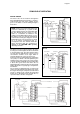
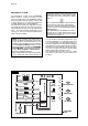
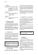
REFRIGERANT CIRCUIT
The hot gas refrigerant discharged out
from the compressor reaches the
condenser where, being cooled down,
condenses into liquid.
Flowing into the liquid line it passes
through the drier filter, then it goes all
the way through the capillary tube where
it looses some of its pressure so that its
pressure and temperature are lowered.
Next, the refrigerant enters into the
evaporator coil wrapped around the
freezer inner tube.
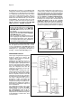
The water being constantly fed at the
interior of the freezer inner tube, exchan-
ge heat with the refrigerant circulating
into the evaporator coil, this cause the
refrigerant to boil-off and evaporate,
thereby it changes from liquid into vapor.
The vapor refrigerant then passes
through the suction accumulator and
through the suction line where the
refrigerant exchanges heat with the one
flowing into the capillary tube (warmer)
before being sucked into the compressor
to be recirculated.
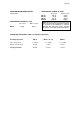
The refrigerant head pressure is kept
between two pre-set values (8÷9 bar -
110÷125 psig on MF 22 and 17÷18
bar - 240÷250 psig on MF 30, MF 46,
MF 56 and MFE 61) by the condenser
temperature sensor which has its probe
located within the condenser fins - in air
cooled versions.
CAPILLARY TUBE
DISCHARGE LINE
COMPRESSOR
FAN MOTOR
EVAPORATOR
MFE 61
ACCUMULATOR
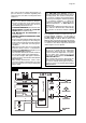
This condenser temperature sensor, when senses
a rising of the condenser temperature beyond
the pre-fixed limit, changes its electrical resistance
and send a low voltage power flow to the MICRO-
PROCESSOR of the P.C. Board which energizes,
through a TRIAC, the Fan Motor in ON-OFF mode.
On the water cooled versions, the refrigerant
head pressure is kept at the constant value of
8.5 bar (120 psig) on MF 22 and of 17 bar
(240 psig) on MF 30, MF 46, MF 56 and MFE 61
by the metered amount of water passing through
the condenser which is regulated by the action of
the Water Regulating Valve that has its capillary
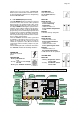
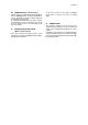
MF 22-30-46-56
ACCUMULATOR
CAPILLARY TUBE
DISCHARGE LINE
EVAPORATOR
FAN MOTOR
COMPRESSOR
CONDENSER
SUCTION LINE
SUCTION LINE
CONDENSER
DRIED
Page 22