
User manual


Appendix
ComTec GmbH 7-4
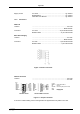
8 Bit DAC - analog signal output
Location: ........................................................................ ref. I/O port connector
Full scale voltage range: (jumper selectable)............................................................. fixed +5V
screw driver adjustable ....................................................+3.5 – +7V
Resolution: .....................................................................................................8 bit
Output current: ......................................................................................... max. 19mA
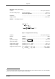
DIGIO 0...7 - 8 bit digital I/O port
Location: ........................................................................ ref. I/O port connector
R PULL : (default) ...................................................................................4.7kΩ
R I/O: (default) ....................................................................................100Ω
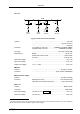
Input HIGH voltage: (at PIN
i
, ref. Figure 7.4)
6
................................................... min. 2.0V
Input LOW voltage: (at PIN
i
) ............................................................................. max. 0.8V
Output HIGH voltage: (at POUT
i
) I
OutHIGH
= -16mA ............................................... min. 2.4V
Output LOW voltage: (at POUT
i
) I
OutLOW
= 15mA .............................................. max. 0.45V
Output short circuit current: V
OUT
= GND (R
PULL
= R
I/O
= 0Ω) ................................-15 to –120mA
V
OUT
= VCC (R
PULL
= R
I/O
= 0Ω) ....................................40 to 210mA
6
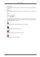
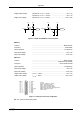
Note: input and output voltages are measured at the internal logic pads not at the external connectors. Thus, the corresponding
pull and series resistors must be considered to get the external voltages
DEN
i
DOUT
i
DIN
i
R PULL
R I/O
DIGITAL I/O
i
POUT
i
PIN
i
Figure 7.4: Digital I/O Port Circuitry