
User manual


Windows Server Program
ComTec GmbH 5-26
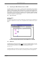
The following commands make sense only when using the serial line or TCP/IP control interface:
MPA? ; Sends the MPA status via the serial port or LAN and make
; MPA actual.
ADC1? ; Sends the status of ADC1 and make ADC1 actual.
...
ADC16? ; Sends the status of ADC16 and make it actual.
? ; Send the status of the actual ADC
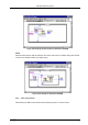
RROI(0,1) ; Sends the sum, mean value and max positive and negative
; deviation from mean of rectangular ROI #1 in spectra #0
PROI(400) ; Sends the sum, mean value and max positive and negative
; deviation from mean value of polygonal ROI with id #400
sendfile filename ; Sends the ASCII file with name ‘filename’ via the serial line.
The execution of a control file can be finished from the Server or MPANT with any Halt command.
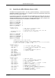
5.3. List file format
The list file starts with an ASCII header containing the settings as described above. The header
ends with a line containing [LISTDATA]. Then the list data follow in binary format. The structure is
as follows:
Every millisecond there is a timer event. It is a 32 bit word containing 0x4000 as high word and as
low word for ADC 1 a 1 in bit 0 if it's "alive" and a 0 if its "dead", the same for ADC2 in bit 1 and
so on. Counting the corresponding set bits directly gives the live time in milliseconds for each
ADC, counting the timer words gives the real time of the run in milliseconds. It is possible that the
timer is written only every 10, 100 or 1000 milliseconds. This is then indicated by a line
"timerreduce=10" (100, 1000, respectively) immediately preceding the [LISTDATA] tag in the
header of the listfile.
After a timer event can follow either again a timer event or a synchronize mark, i.e. a double word
containing 0xFFFFFFFF and then event data.
Event data start always with a event signal double word containing in the high word some flags
and a zero in bit 30 (to distinguish it from a timer event), and in the low word for each ADC that
has data a 1 in the corresponding bit (bit 0 for ADC1 ...). The ADC data are 16 bit and the data
structure is in a 32 bit raster, therefore there must be a 16 bit dummy word inserted for an odd
number of ADCs containing data to get an even number of 16 bit data words. If such a dummy
was inserted, this is marked in bit 31 of the event signal word. If data of the 48 bit real time clock
(RTC) are in the event, this is marked in bit 28 of the event signal word.
If RTC data are signaled in the event signal double word, the three 16 bit RTC data rtc0, rtc1 and
rtc2 follow immediately after the signal word in the next low, high and low words. The rtc value is
(rtc2 * 65536 + rtc1) * 65536 + rtc0. It starts from a (preset) value that can be set by software and
counts down with 20 MHz (or extern clock). After rtc2 follows in a high word the dummy word if bit
31 in the event signal double word was set, or ADC data.
If RTC data were not signaled, immediately after the signal double word follows in the next low
word either a dummy word (if signaled in bit 31) or ADC data (starting from the lowest ADC that
has data). From the signal double word it is clear how many ADC data follow and also that it is an
even number of 16 bit words, so after this set of data can either again follow a new set starting
with a new event signal double word, or a new live time event.