
User manual

Windows Server Program
ComTec GmbH 5-9
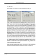
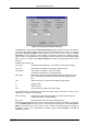
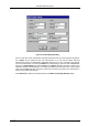
The RTC can insert 48 bit timer data into the listdata stream. Check Timestamp in datastream
to enable it. The timer starts from a defined preset value that can be defined in the Preset edit
field together with the Unit selection listbox and counts down. It is possible to stop the
measurement after the preset time by enabling Halt when preset reached. The time unit for the
preset can be nsec, µsec, msec, sec and h. The timer runs usually with 20 MHz, but the Count
Source can be selected between the internal 20 MHz timer or an external counter or clock taken
from the edge of a signal input at the AUX1, AUX2 or REJ connectors. The Timer runs when the
acquisition is ON or gated by 'AUX2 and ON', 'AUX1 and ON' or 'REJ and ON' as selected from
the respective selection box. Preset load Mode defines the start time. It can be 'Software only'
i.e. start together with the acquisition, or an extern signal from AUX2, AUX1, REJ, or 'wrap
around' i.e. the counter starts immediately again with the preset value after zero was reached.
Please check the polarity of the AUX input signal in the Auxiliary connectors dialog, if you use any
of the auxiliary connectors for timer load or -capture. The Time Capture defines when the RTC
value is inserted into the datastream. It can be selected between OR'ed DEAD (DOR), DOR or
AUX2, DOR or AUX1, DOR or REJ, Coinc Start, Coinc End, Coinc OK (it is equivalent to Coinc
End) and 'Software only' (presently not used). The ORed DEAD of ADC is explicitly defined by a
checkbox for each available ADC input. So for each ADC individually can be set that its DEAD
time signal may capture a timer value into the data stream.
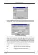
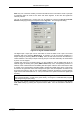
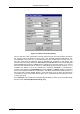
The „Remote mode...“ item in the settings menu or the „Remote“ button in the System Definition
dialog box opens the Remote Control dialog box. Here all settings can be made for the control of
the MPA-3 server program via a serial port.
Figure 5.11: Use of Real Time Clock