
User manual

Windows Server Program
ComTec GmbH 5-8
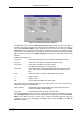
Note: only one of the three auxiliary connectors should be used in coincidence mode. In principle
it sometimes might be useful to use AUX1 and AUX2 together. In this case the signals are
internally "OR"ed.
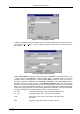
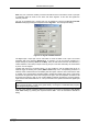
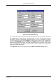
The use of the digital input / output ports can be defined by opening the Dig IO and DAC
definition dialog by pressing the respective button Dig, DAC... from the systems dialog.
The digital input / output port can be used either to show the status in bit 0 (bit 0 set means
acquisition ON) if the checkbox Status Dig 0 is checked, or it can be used for example for a
sample changer by checking Value inc. at Stop . Here, the 8 bit value entered in the edit field ( a
number between 0 and 255) is output at the Dig I/O port. This value will always be incremented
by one if a run is stopped.
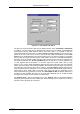
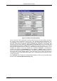
Together with using bit 0 as status signal, it is also possible to use the digital input #6 as an
external trigger for starting the system (DESY control line). If the corresponding checkbox is
marked, a start command will not immediately start the system. After the start command, the data
is cleared if the corresponding checkbox Clear is marked and digital input will be continuously
checked for its logical level. If the level changes from high to low, the acquisition is started. It will
stop if the level returns to high (or vice versa if Invert is marked), and with the next level change
again cleared and restarted and so on. A stop command for the system will finish the digital input
checking.
NOTE: It is recommended to disable DMA mode by setting nodma=1 in the MPA3.INI file and
running the MPA3.EXE in normal priority (start directly, not using the LAUNCHMP.EXE program)
when using this Dig 6 input polling.
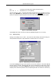
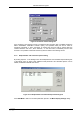
The use of the optional Timestamp Real time clock RTC can be set by opening the Use of Real
Time Clock dialog by pressing the respective button RTC... from the Coincidence Definitions
dialog.
Figure 5.10: Dig I/O and DAC Definition