
User manual


Functional Description
ComTec GmbH 4-3
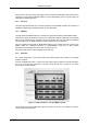
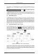
The control signals to the timer are derived from a logic OR of the enabled input signals.
Particularly 'TIMER_COUNT' may be derived from a large variety of signals (ref. chapter 5.1.5 for
more details) incl. all DEADTIME signals and the AUX connectors.
'TIMER_COUNT' is selectable from:
• 20MHz clock (real time with 50ns resolution)
• pos./neg. edge of AUX 1
• pos./neg. edge of AUX 2
• pos./neg. edge of REJECT
'TIMER_LOAD' is selectable from:
• Software only
• low/high of AUX 1
• low/high of AUX 2
• low/high of REJECT
• Wrap around (reloads the preset value when zero is reached)
'TIMER_ENABLE' is selectable from a logic AND of 'SYSTEM ON' and AUX 1, AUX 2 or REJECT
respectively.
'REGISTRATE COUNTER' is selectable from:
• logic OR-ed edges of any selected DEADTIME signals. Also edges of AUX 1, AUX 2 or
REJECT may be included
• internal coincidence start signal
• internal coincidence end (finished) signal
Whenever a 'TIMER_LOAD' is asserted also a 'REGISTRATE COUNTER' command is executed.
On reaching 0 (zero) 'PRESET REACHED' goes TRUE and if a preset is enabled the counter is
stopped.
Figure 4.2: Logic Schematic of Timer Control Signals