
User manual


Functional Description
ComTec GmbH 4-2
timeout elapsed – the corresponding ports are read and the data is transfered to the PC in
listmode. If a port has no new data (BUSY is still false when timeout occurs) a zero is transfered
for this port.
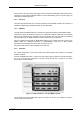
The ADC ports that are allowed to open a coincidence time window are software selectable (ref.
Figure 5.8: Coincidence Definition dialog box on page 5-6). This enables for further data
reduction.
In COINCIDENCE mode of operation the corresponding ADC ports accept new data only when a
coincidence time window is open. This is usefull to reduce the system deadtime caused by not
coincident or unwanted ADC events. This is why in this mode the DEADTIME signals must
precede the corresponding DRDYs by at least 200ns.
4.4. DEADTIME Detection
The DEADTIME signals coming from the ADCs are synchronized to the internal 10MHz clock
provided at each ADC port. Then they are transfered to the BASE module where in conjunction
with an edge detection the coincidence resolving is processed. Furthermore every one
millisecond all the inverted DEADTIME signals (i.e. the LIVETIME signals) are sampled and the
result is transmitted to the PCI card. Thus, every millisecond an image of the DEADTIME state of
all connected ADCs is inserted into the listmode data stream. On the one hand this provides time
stamps every 1ms in the data stream and on the other hand also a statistical means for
LIVETIME correction with a resolution of one millisecond.
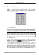
4.5. 48 bit RealTimeClock / Timer / Counter
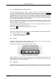
The 48 bit RealTimeClock (RTC) / Timer / Counter is built from a 48 bit synchronuous down-
counter. Any time 'TIMER_LOAD' (ref. Figure 4.1) is TRUE the counter is loaded with the stored
preset value. When 'TIMER_LOAD' is FALSE and 'TIMER_ENABLE' is TRUE the counter is
decremented with a 50ns cycle time whenever 'TIMER_COUNT' is TRUE. While 'TIMER_LOAD'
and 'TIMER_ENABLE' are level sensitiv signals 'TIMER_COUNT' goes TRUE for 50ns on every
detected edge of the appropriate source signals (ref. chapter 5.1.5).
As can be seen the actual counter contents is read into the capture register on the registrate
(capture) counter command. Then it is shifted into the transfer register. During a timer data
transfer into the computer being in progress the transfer register is disabled (locked) to prevent
changing the data while a read cycle is still active. This is necessary since the 48 bit data is in
fact read in three subsequent 16 bit operations.
Figure 4.1: RealTimeClock / Timer / Counter Schematic