
User manual


Hardware Description
ComTec GmbH 3-9
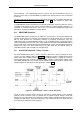
D0...15 - Active low data input signals
DRDY - Data Ready input signal indicating that valid data is present at the ADC port. The polarity
is software selectable.
DACC - Data Accepted output signal. Indicates that the input data is registered. The polarity is
software selectable.
DEAD TIME - Dead Time input signal. The polarity is software selectable.
ENC - Enable Converter output signal to arm the connected ADC, TOF, etc. The polarity is
software selectable.
DENB - Output signal to enable a tri-state data output driver of the ADC, TOF, etc. The polarity is
software selectable.
The handshake is quite easy: when the ADC asserts a DRDY the port registers the valid ADC
data and then signals a DACC. After that the ADC removes DRDY and the module then
deasserts DACC.
In COINCIDENCE mode of operation after the data being registered ENC (enable converter) is
deasserted to prevent the ADC from further conversions before the coincidence resolving time
and the processing of the actual coincidence event has ended.
In COINCIDENCE mode it is required that DEADTIME preceeds DRDY by at least 200ns (ref.
also chapter 4.3).
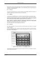
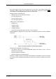
D0 - 1
D1 - 2
D2 - 3
D3 - 4
D4 - 5
D5 - 6
D6 - 7
D7 - 8
D8 - 9
D9 - 10
D10 - 11
D11 - 12
D12 - 13
14 - DRDY
15 - D13
16 - D14
17 - DACC
18 - ENC
19 - D15
20 - GND
21 - DEAD TIME
22 - DENB
23 - GND
24 - GND
25 - GND
Legend:
D0...D15 = Data Bit 0...15 (input)
DRDY = Data Ready (input)
DACC = Data Accepted (output)
ENC = Enable Converter (output)
DEAD TIME = ADC Dead Time Signal (input)
DENB = Data Enable (output)
GND = Ground
Figure 3.11: 25 pin D-SUB ADC port connector