
User manual


Hardware Description
ComTec GmbH 3-8
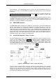
3.3.9. 48 bit RealTimeClock / Timer / Counter
The 48 bit RealTimeClock (RTC) / Timer / Counter is built from a 48 bit synchronuous down-
counter. To enable reliable capture and read operation a pipeline of two registers (ref. Figure 4.1)
is provided. As can be seen the actual counter contents is read into a capture register on the
registrate (capture) counter command. Then it is shifted into the transfer register. During a timer
data transfer into the computer being in progress the transfer register is disabled (locked) to
prevent changing the data while a read cycle is still active. This is necessary since the 48 bit data
is in fact read in three subsequent 16 bit operations.
Whenever 'TIMER_LOAD' is asserted also a 'REGISTRATE COUNTER' command is executed
which overwrites possible old data and ensures that on a subsequent transfer operation only data
from the actual timer cycles is used.
On reaching 0 (zero) 'PRESET REACHED' goes TRUE and, if a preset is enabled, the counter is
stopped. Also, if selected, the GO-line is reset.
Refer chapter 4.5 for a detailed description of the timer functions.
3.3.10. ADC Ports
These are four standard nuclear ADC interface ports with DataReady / DataAccepted handshake.
For a detailed description refer chapter 3.4.2.
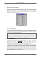
3.4. Quad ADC Port Module
3.4.1. General
The MPA-3 Quad ADC Port module provides an interface for to up to four nuclear ADCs,
Multiscalers, Position Analyzers, Time-of-Flight units etc.
Up to three such modules might be installed in a MPA-3 system.
During initialization a module number is assigned to each MPA-3 Quad ADC Port module. This
module number is shown on a seven segment display on the frontside of the module. Thus, the
individual ADC ports can be easily identified.
3.4.2. ADC Ports
The MPA-3 ADC ports support up to 16 bit (64k channel) ADCs, TOFs etc. Since all control signal
polarities are software selectable almost any known nuclear ADC, TOF etc. might be connected.
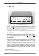
Figure 3.10: Quad ADC Port module