
User manual


Hardware Description
ComTec GmbH 3-7
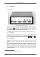
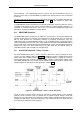
The 'BUSY' is on (red) when either data is being transferred to the PC or when a coincidence
event is processed. Thus, it gives a quick indication of the system load.
Finally, a seven segment display shows the module number assigned to the Quad ADC Port type
module already included in the BASE module. After power up it will show an '8'. After software
start the connected modules are initialized and module numbers are assigned to each individual
module. These module numbers are displayed on the seven segment display and help to identify
the individual ADC ports. Example: when an '1' is assigned the ADC ports of the very module will
mean 'ADC 1A', 'ADC 1B', 'ADC 1C' and 'ADC 1D' (from left to right).
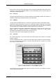
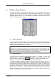
3.3.7. Auxiliary I/O Connectors
Two BNC type connectors AUX 1 & 2 located on the front of the BASE module.
The auxiliary connectors provide two additional bidirectional ports. These can be used for a
variety of software configurable features (ref Figure 5.9: Auxiliary Connectors dialog box).
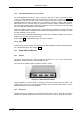
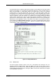
3.3.8. REJECT Input
The REJECT input also is a BNC type connector located on the frontside of the MPA-3 BASE
module. It provides additional flexibility in COINCIDENCE mode of operation (ref. Figure 5.9:
Auxiliary Connectors dialog box on page 5-7).
VCC
4k7
100R
AUX
i
VCC
AUX
i
I/O
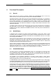
Figure 3.8: Auxiliary I/O circuitry
VCC
4k7
1k0
REJ ECT
VCC
REJECT I N
22p
Figure 3.9: REJECT input circuit schematic