
User manual

Hardware Description
ComTec GmbH 3-3
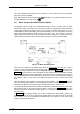
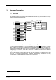
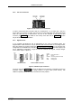
3.2.2. 'GO' Line Connector
In order to synchronize other computer cards to a measurement - e.g. a scaler card - there is a
two pin 'GO' line connector on board. The 'GO' line is a system wide open drain wired-AND signal
which can start and stop a measurement. This line is also available on the Multi I/O port
connector (ref. Figure 3.4). For details on the circuitry of the 'GO' line ref. Figure 7.5. This line
may be set and reset by the software.
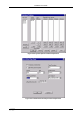
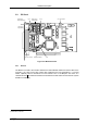
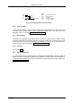
3.2.3. Digital I/O Port
A very versatile 8 bit digital I/O port is implemented on the 16 pin four-walled header. The
supplied ribbon cable connects to a 15 pin female D-SUB connector fixed on a mounting bracket.
Since the resistors are socket mounted (ref. Figure 3.2: MPA-3 PCI Card) they can be easily user
configured in a most flexible way. This I/O port is fully software controllable and each single (1 bit)
port is individually configurable. It might be used for external alert signals, sample changer
control, status inputs / outputs etc.
As can be seen from Figure 3.5 each bit of the digital I/O port might be configured as input only
(tri-stated output), pull-up, pull-down (large R PULL) or driver output (small R PULL) with
readback capability. Wired-OR / AND connections are also possible.
Figure 3.3: PCI Card GO Line Connector
fixed
onboard header female D-SUB connector
1
3
5
7
9
11
13
15
GO
DIGIO 0
DIGIO 2
DIGIO 4
DIGIO 6
GND
8 Bit DAC
V
CC
-
-
-
-
-
-
-
-
2
4
6
8
10
12
14
16
GND
DIGIO 1
DIGIO 3
DIGIO 5
DIGIO 7
AGND
AGND
AGND
-
-
-
-
-
-
-
-
Legend:
DIGIO 0...7
GO
8 Bit DAC
GND
AGND
= Digital I/O Port Bit 0...7
= Go-Line
= 8 bit analog output (0..5V or 6,5V)
= Digital ground
= Analog ground
1
2
3
4
5
6
7
8
GO
DIGIO 0
DIGIO 2
DIGIO 4
DIGIO 6
GND
8 Bit DAC
VCC
-
-
-
-
-
-
-
-
9
10
11
12
13
14
15
GND
DIGIO 1
DIGIO 3
DIGIO 5
DIGIO 7
AGND
AGND
-
-
-
-
-
-
-
Figure 3.4: Multi I/O port connector