MPA-3 Multiparameter Data Acquisition System User Manual copyright FAST ComTec GmbH Grünwalder Weg 28a, D-82041 Oberhaching Germany Version 1.
Warranty Information Warranty Information FAST ComTec assures that all the data and descriptions in this manual are made to the best of our knowledge. FAST ComTec is not liable for technical or editorial errors or omissions made herein. The features and specifications described in this manual are subject to change without notice. FAST ComTec warrants proper operation of the software only when used with software and hardware supplied by FAST ComTec.
Important Information on Hardware Compatibility Important Information on Hardware Compatibility The MPA-3 Multiparameter Systems are PCI Local Bus compliant devices. As such the board contains the configuration space register organization as defined by the PCI Local Bus Specification. Among the functions of the configuration registers is the storage of unique identification values for our devices as well as storage of base address size requirements for correct operation specific to each of our products.
Table of Contents Table of Contents 1. Introduction .............................................................................................................................. 1-1 2. Installation Procedure .............................................................................................................. 2-1 2.1. Hard- and Software Requirements ............................................................................. 2-1 2.2. Hardware Installation .........................................
Table of Contents 5.6. 5.5.4. Close Conversation ...................................................................................... 5-30 Controlling the MPA-3 Windows Server via DLL ...................................................... 5-32 6. MPA-NT Software .................................................................................................................... 6-1 6.1. File Menu ............................................................................................................
Table of Figures Table of Figures Figure 1.1: BASE + 3 Quad ADC Port modules MPA-3 system................................................... 1-1 Figure 2.1: 16 port MPA-3 system ................................................................................................ 2-1 Figure 2.2: MPA-3 PCI Card ......................................................................................................... 2-2 Figure 2.3: add-on I/O port connector..........................................................
Table of Figures Figure 5.18: Sum of counts spectra before and after calibration................................................ 5-14 Figure 5.19: DLL Function Dialog ............................................................................................... 5-15 Figure 5.20: Conditions ............................................................................................................... 5-16 Figure 5.21: ROI Conditions dialog....................................................................
Introduction 1. Introduction The MPA-3 Multiparameter System is an ultra fast listmode multichannel data acquisition system featuring data rates and performance previously not known in commercially available multiparameter systems. The MPA-3 system is designed to handle up to 16 external ADCs, multiscalers or time-of-flight units. The open system technology is capable to easily accommodate future system expansions.
Introduction With the presettable 48 bit RealTimeClock / Timer / Counter (optional) a variety of additional information can be captured. E.g. timestamps may be inserted into the datastream to obtain detailed information on the time particular events have occurred - with a resolution of upto 50ns. Also scaler, multi spectra scaling, multiscaling, Time-of-Flight applications etc. may be realized since a large variety of load, reset, capture, readout options is available.
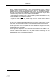
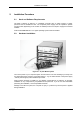
Installation Procedure 2. Installation Procedure 2.1. Hard- and Software Requirements The MPA-3 requires an IBM AT or compatible computer with an I486, Pentium or higher processor and an available PCI slot. The computers power supply must be capable to provide enough current (depending on the number of modules) from its 5V output to supply all connected modules. A Microsoft WINDOWS NT 4.0 or higher operating system must be installed. 2.2. Hardware Installation Figure 2.
Installation Procedure PCI Interface Card Figure 2.2: MPA-3 PCI Card Open the computer case's cover and insert the MPA-3 PCI card in an unused PCI slot. You might first have to remove the cover from the rear of the PCI expansion slot you selected. After the card is carefully seated in the PCI slot, make sure you fastened the card with a screw on the mounting bracket. Figure 2.3: add-on I/O port connector Now install the add-on I/O port connector.
Installation Procedure Extra Power Supply Connector Figure 2.4: Extra power supply connector The 'Extra Power Cable' is necessary if any MPA-3 Quad ADC Port Module is connected with the Base Module and is usually delivered with systems containing such a module. Find an available mounting place on the rear of your PC. Mount the slot bracket with 9 pin female D-SUB connector and plug in the floppy type power connector. MPA-3 BASE Module Figure 2.
Installation Procedure special cables are optionally available. Be sure the screws at the D-SUB connectors are tightened. If you have purchased the 'Extra Power Cable' also connect it to the 9 pin female D-SUB 'Extra Power Supply' connector previously installed in the computer and to the 9 pin male D-SUB connector named 'POWER IN' on the rear of the MPA-3 BASE module. MPA-3 Quad ADC Port Modules Figure 2.
Installation Procedure Now the FMP bus is to be connected. This is done from the right bottom to the left top. Any Quad ADC Port module is delivered with such a short 50 core CENTRONIX cable that connects this module to the next module towards the BASE module. Always connect the 'FMP BUS OUT' of the lower module to the 'FMP BUS IN' of the upper one (ref. Figure 2.7). Be sure to close the side clips of the CENTRONIX connectors. 2.3.
Installation Procedure Figure 2.8: MPANT program startup screen Now we have to change the system settings to one ADC (default is four) only. Open the System... menu in the Options pull-down menu (see Figure 2.8). Figure 2.9: 'Coincidence Definition' dialog with one SINGLE ADC Now the Coincidence Definition window should look like Figure 2.9. Close the window with OK. The MPANT window will change to display one ADC window only (ref. Figure 2.10).
Installation Procedure Remove ADC1B, ADC1C and ADC1D from the Singles no coinc. by just clicking on them. If you accidentally removed ADC1A bring it back to the Singles no coinc. field by selecting it with one click and moving it by a click on >> below the Singles no coinc. box. No we must set the range of the ADC to 1k. For this, open Options – Range, Preset... Change the ADC Settings – Range to 1k = 1024 (ref. Figure 2.11) and click OK.
Installation Procedure Figure 2.11: Set ADC range to 1k range Now start data acquisition by a click on the START button (ref. Figure 2.12). Recognize that when you move the mouse pointer over a button a help message appears in the lower left corner of the MPANT window. In this case it is 'Erases and starts a measurement' meaning that the contents of the histograms is erased and then a new acquisition is started. Click OK in the message window that appears after clicking the START button.
Installation Procedure Figure 2.12: START a SINGLE measurement with one ADC See that the Status changes to ON. The Real time will begin to run also indicating that data acquisition is ON. Depending on your input signals a histogram should start to be accumulated (ref. Figure 2.13). When you want to finish data acquisition click on the STOP button . The corresponding help message is 'Halts a measurement'.
Installation Procedure Figure 2.13: Spectrum of a basic SINGLE measurement 2.5. Getting Started with a basic COINCIDENCE measurement What we are going to do is to setup a basic COINCIDENCE measurement using two ADCs. The ADCs will be set to a conversion gain of 4k. The on-line displays are set to a single spectrum for each ADC and a two-dimensional spectrum of ADC1A x ADC1B with a resolution of 256 x 256 channels. First open the Coincidence Definition window by a click on the System options button .
Installation Procedure Figure 2.14: Setup two ADCs for a COINCIDENCE measurement Set the ADC ranges to 4096 using the Range, Preset… button to get into the ADC Settings and Preset window. Set the Coinc time to 10.00µs using the scrollbar. Then click into the data field of DRDY Timeout and type in 50.00 to set the DRDY timeout to 50.00µs. This is in accordance to a 100MHz Wilkinson type ADC (4k x 10ns ≈ 40µs + 10µs overhead for safety) like our model 7074 Quad ADC.
Installation Procedure Figure 2.15: Setup ADC range and coincidence resolving time Now we will still have to define a two-dimensional spectrum of ADC1A x ADC1B. Open the spectra definition window Dualparameter and Calculated spectra by a click on the Spectra button . In the Map and Calculated spectra window click on Add Multi… button to add a new multiparameter spectrum. The Multi Display Setting window opens. Figure 2.
Installation Procedure Figure 2.17: New spectrum defined Close Dualparameter and Calculated spectra and the MPANT display should show up with two single spectra (ADC1A and ADC1B) and one multiparameter map (ref. Figure 2.18). Figure 2.18: Two single and one multiparameter spectra display Connect input signals to the ADCs.
Installation Procedure but in the map display they will show up on the base of x- and y-axis (zero) since the respective other ADC is read as a 'ZERO'. Start data acquisition with the START button End data acquisition by a click on STOP . 2.6. . Depending on your signals spectra are shown. Basic Usage of the RealTimeClock Option To familiarize with the usage of the 48 bit RealTimeClock / Timer / Counter option a simple experiment is setup.
Installation Procedure Figure 2.20: System Options for RTC Experiment Figure 2.
Installation Procedure Figure 2.22: Auxiliary Connectors Setup for basic RTC Measurement Figure 2.
Installation Procedure Figure 2.
Hardware Description 3. Hardware Description 3.1. Overview The modular concept of the MPA-3 system is designed to enable easy accommodation to a huge variety of experimental requirements.
Hardware Description 3.2. PCI Card R I/O Analog Output Range Potentiometer Analog Output Range Selector Digital I/O Port onboard Header R Pull GO- Line Connector 3V-7V 5V 3 2 1 WP. FHS- Link Connector Write Protect Selector Fuse Figure 3.2: MPA-3 PCI Card 3.2.1. General The MPA-3 PCI Card is the interface between the MPA-3 BASE module and the PCI Bus of the computer. It is a short 5V PCI bus master card compliant to the PCI specification 2.1.
Hardware Description 3.2.2. 'GO' Line Connector Figure 3.3: PCI Card GO Line Connector In order to synchronize other computer cards to a measurement - e.g. a scaler card - there is a two pin 'GO' line connector on board. The 'GO' line is a system wide open drain wired-AND signal which can start and stop a measurement. This line is also available on the Multi I/O port connector (ref. Figure 3.4). For details on the circuitry of the 'GO' line ref. Figure 7.5. This line may be set and reset by the software.
Hardware Description DENi DOUTi R Pull R I/O DINi Digital I/Oi Legend: DEN DOUT DIN R Pull R I/O = Data output driver enabl e = Data output driver = Data input = 4.7 kOhms (default) = 100 Ohms (default) Figure 3.5: Digital I/O port circuit schematic 3.2.4. Analog Output A 8 bit Digital-to-Analog converter provides a software programmable analog output voltage. The full scale output voltage range is jumper selectable between fixed +5V and screw driver adjustable +3,5V to +7V. (Ref. Figure 3.
Hardware Description 3.3. BASE Module 3.3.1. General Figure 3.6: BASE module front view The MPA-3 BASE module is the heart of the MPA-3 multiparameter system. It provides the interface to the PC as well as the interface to the subsequent modules which, so far may be up to three Quad ADC Port4 modules. Besides, the BASE module already includes four ADC ports for the connection of external ADCs, Multiscalers, Position Analyzers, Time-of-Flight units etc.
Hardware Description When the PC is turned off the power supply connection between the BASE module and the PC is opened by a relay inside the BASE module to prevent backloading of the PC power supply by externally connected electronics. 3.3.4. FHS Link The FAST High Speed (FHS) Link connects the MPA-3 frontend BASE module to the computer. It provides full duplex high speed data transfer at up to 420 Mbit/s. 3.3.5.
Hardware Description The 'BUSY' is on (red) when either data is being transferred to the PC or when a coincidence event is processed. Thus, it gives a quick indication of the system load. Finally, a seven segment display shows the module number assigned to the Quad ADC Port type module already included in the BASE module. After power up it will show an '8'. After software start the connected modules are initialized and module numbers are assigned to each individual module.
Hardware Description 3.3.9. 48 bit RealTimeClock / Timer / Counter The 48 bit RealTimeClock (RTC) / Timer / Counter is built from a 48 bit synchronuous downcounter. To enable reliable capture and read operation a pipeline of two registers (ref. Figure 4.1) is provided. As can be seen the actual counter contents is read into a capture register on the registrate (capture) counter command. Then it is shifted into the transfer register.
Hardware Description D0 - 1 D1 - 2 D2 - 3 D3 - 4 D4 - 5 D5 - 6 D6 - 7 D7 - 8 D8 - 9 D9 - 10 D10 - 11 D11 - 12 D12 - 13 14 - DRDY 15 - D13 16 - D14 17 - DACC 18 - ENC 19 - D15 20 - GND 21 - DEAD TIME 22 - DENB 23 - GND 24 - GND 25 - GND Legend: D0...D15 = Data Bit 0...15 (input) DRDY = Data Ready (input) DACC = Data Accepted (output) ENC = Enable Converter (output) DEAD TIME = ADC Dead Time Signal (input) DENB = Data Enable (output) GND = Ground Figure 3.11: 25 pin D-SUB ADC port connector D0...
Functional Description 4. Functional Description 4.1. General Basicly there exist two modes of operation: SINGLE and COINCIDENCE and of course any mixture of both. The mode of operation of each port is individually selectable. Generally all transfer of ADC data to the PC is done blockwise and in listmode, i.e. one after the other with some overhead. The overhead consists of words for synchronization purposes and some header information.
Functional Description timeout elapsed – the corresponding ports are read and the data is transfered to the PC in listmode. If a port has no new data (BUSY is still false when timeout occurs) a zero is transfered for this port. The ADC ports that are allowed to open a coincidence time window are software selectable (ref. Figure 5.8: Coincidence Definition dialog box on page 5-6). This enables for further data reduction.
Functional Description The control signals to the timer are derived from a logic OR of the enabled input signals. Particularly 'TIMER_COUNT' may be derived from a large variety of signals (ref. chapter 5.1.5 for more details) incl. all DEADTIME signals and the AUX connectors. 'TIMER_COUNT' is selectable from: • 20MHz clock (real time with 50ns resolution) • pos./neg. edge of AUX 1 • pos./neg. edge of AUX 2 • pos./neg.
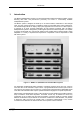
Windows Server Program 5. Windows Server Program The window of the MPA-3 server program MPA3.EXE is shown here. It enables the full control of the MPA-3 to perform measurements and save data. This program has no own graphic capabilities, but it provides - via a DLL ("dynamic link library“) - access to all functions, parameters and data. The server can be completely controlled from the MPANT software that provides all necessary graphic displays. Figure 5.1: MPA-3 Server 5.1.
Windows Server Program Two parameters allow to define the DMA transfer settings. 'timeout' defines the time after a DMA transfer is terminated if it is not finished, and 'blocksize' defines the number of double words of data to be transmitted in a single DMA transfer. The default value of 1024 is for moderate counting rates. For very high counting rates you may chose a value like 4096 or 16384. One special thread in the software handles only the DMA transfer.
Windows Server Program 5.1.3. File menu Clicking in the File menu on the Data... item opens the Data Operations dialog box. Figure 5.3: Data Operations dialog boxes for MPA data (left) and selected spectra (right) This dialog allows to edit the data format settings and perform operations like Save, Load, Add, Subtract, Smooth and Erase.
Windows Server Program Figure 5.4: The Log Options dialog If Replay is enabled in the MPA3 Base module or the Replay Keymodule is connected to LPT1, the menu item File – Replay... opens the Replay dialog (see above for the correct entry in the mpa3.ini file). Figure 5.5: Replay Settings dialog Enable Replay Mode using the checkbox and specify a Filename of a list file (extension .LST) or search one by pressing Browse...
Windows Server Program EC 5 ; Coincidence event flag, data in ADC0 and ADC2 (hex 5) RTC 576 0 0 ; RTC data rtc0, rtc1, rtc2 (decimal) The menu item File – About... opens the About MPA3 window where some information of the very MPA-3 System can be found. Particularly the serial number (ref. Figure 5.6 above the mouse pointer) is important for support purposes. This serial number is unique for each MPA-3 system. Figure 5.
Windows Server Program if they are within the ROI5 limits, i.e. >= the lower limit and < the upper limit. Another possibility is to acquire data for a given run time via the RTimepreset or a given live time via the LTimepreset. A measurement will be stopped if the corresponding checkbox is marked. The width of the coincidence window can be set between 0.15 and 3276 µsec in steps of 50 nsec by entering the number or using the scroll bar. The Data Ready Timeout can be set within the same limits.
Windows Server Program Figure 5.9: Auxiliary Connectors dialog box The Aux conn... button opens the Auxiliary Connectors dialog to define the use of the auxiliary connectors. The AUX1 and AUX2 connectors both can be used either as an input or an output. In input mode Coincidence Mode must be checked to get it into the 'coinc. with any' list. Start Coincidence can be checked to allow starting a coincidence resolving time window from the input connector.
Windows Server Program Note: only one of the three auxiliary connectors should be used in coincidence mode. In principle it sometimes might be useful to use AUX1 and AUX2 together. In this case the signals are internally "OR"ed. The use of the digital input / output ports can be defined by opening the Dig IO and DAC definition dialog by pressing the respective button Dig, DAC... from the systems dialog. Figure 5.
Windows Server Program Figure 5.11: Use of Real Time Clock The RTC can insert 48 bit timer data into the listdata stream. Check Timestamp in datastream to enable it. The timer starts from a defined preset value that can be defined in the Preset edit field together with the Unit selection listbox and counts down. It is possible to stop the measurement after the preset time by enabling Halt when preset reached. The time unit for the preset can be nsec, µsec, msec, sec and h.
Windows Server Program Figure 5.12: Remote Control dialog box If the Checkbox „Use Remote Control“ is marked and the necessary DLL is available (Order the MPA-3 EXTERNAL CONTROL software option), the specified COM port will be used for accepting commands. If „Echo command“ is marked, the input line will be echoed after the newline character was sent. „Echo character“, on the other hand, immediately echoes each character. The possible commands and their syntax are listed in the following section. 5.1.6.
Windows Server Program Figure 5.14: Multi Display Setting For the x Axis and y Axis a parameter and range must be chosen from the respective drop down list. A Name can be entered for the new multi spectra, or you can left the 'Name' edit field untouched to choose an automatically generated name like 1A x 1B. If Conditions are defined, one can be selected as a necessary Condition for incrementing a channel in this dualparameter spectra.
Windows Server Program Figure 5.15: Multi Time Display Setting For the x Axis and y Axis a parameter and range must be chosen from the respective drop down list. The time axis can be either the x Axis or the y Axis, select the respective radio button. The time parameter can be either the 1 msec Real time from the standard real / live timer or the 50 nsec RTC clock when the respective option is available and 'Timestamp in data stream' was checked in the RTC dialog.
Windows Server Program Figure 5.16: Calculated Spectrum Setting You have a choice between several formulas to combine two ADC parameters: Pos = Range * right / (left + right) is a formula often used with position sensitive detectors read out from both sides. Sum = left + right makes a sum spectrum, and Div = Range * left / right can be used to divide two spectra. The Range and Name can be defined in the edit fields or default values will be taken.
Windows Server Program In the "Sum of counts" dialog you can select which ADCs will contribute to the superdetector. It is recommended to enable "Use Calibration" and to perform a careful calibration of all selected ADC's: Make a short acquisition using a pulser or a calibration source so you get a peak in each used ADC.
Windows Server Program By selecting "DLL function" and pressing the Edit... button a dialog "Dll Function" is opened. Figure 5.19: DLL Function Dialog The calculated spectrum is a function programmed in the DMPA3.DLL, for example RTab(Xpar, Ypar, Zpar). Xpar is the "left" parameter, Ypar the "right" parameter. Run the TSTRXY.EXE program to create a sample table file and try the dlltest.
Windows Server Program Figure 5.20: Conditions To define a new condition, press Add... to open the ROI Condition dialog. Figure 5.21: ROI Conditions dialog Here it is possible to define a Condition as an event inside or outside of an ROI in any spectra. There are two drop-down list boxes for the Parameter and ROI. Of course the ROI must be defined before by using the MPANT program, it is not possible here to add any new ROI.
Windows Server Program Figure 5.22: Combine Conditions dialog Here it is possible to define a Condition as a combination using the Boolean operators NOT, OR or AND of already defined conditions. The OR will be symbolized in the automatically generated name by a plus sign "+", the AND by an asterisk "*".
Windows Server Program 5.2. Control Language A sequence of commands that are stored in a file with extension .CTL can be executed by the MPA-3 server program or MPANT with the „Load “ command. Also the configuration files MPA3.CNF or the header files with extension .MP contain such commands to set the parameters. Each command starts at the beginning of a new line with a typical keyword, the case is ignored. Any other characters in a line may contain a value or a comment.
Windows Server Program The file MPA3.CNF contains a complete list of commands for setting parameters; an example is: wndwidth=237 ; Sets width of server window wndheight=263 ; Sets height of server window loglevel=7 ; controls the logging of actions into the log file (hex format): ; bit 0 = 1 START, bit 1 = 1 STOP, bit 2 = 1 SAVE are ; protocoled with time into the logfile.
Windows Server Program autoinc=0 ; 1=Enable Auto increment of filename savedata=0 ; 1=Save at Halt mpafmt=dat ; data format used in MPA files ; (dat=binary, asc=ASCII, spe=GANAAS) sephead=0 ; 1=Seperated Header file (extension MP) and ; Data file (extension dat, asc or spe) for seperated spectra fmt=dat ; data format used in seperated spectra (extension MP) ; (dat=binary, asc=ASCII, spe=GANAAS) smoothpts=5 ; Number of points to average for a smooth operation [ADC1] ; The following section conc
Windows Server Program [MAP0] 1A x 1B ; The following section concerns parameters of a MAP spectra ; named 1A x 1B, the number 0 is an index starting at 0 for the ; first calculated spectra param=10000 ; Paramer definition (hex): the lower word defines the x-axis ; parameter (here 0 == ADC1A), the higher word the y axis (here ; 1 == ADC1B) ...
Windows Server Program mpafmt=dat sephead=1 fmt=dat smoothpts=5 [ADC0] REPORT-FILE from 11/03/86 08:00:00 written 09/02/98 16:51:04 ; the first time is when the measurement was started, nd ; the 2 when the data file was written realtime=0.00 ; real time in seconds livetime=0.
Windows Server Program roi=1961 1988 roi=2909 2925 roi=2924 2943 roi=4036 4055 roi=2573 2590 The following commands perform actions and therefore usually are not included in a MPA3.CNF file: start ; Clears the data and starts a new acquisition. Further ; execution of the .CTL file is suspended until any ; acquisition stops due to a preset. halt ; Stops acquisition if one is running. cont ; Continues acquisition.
Windows Server Program erasedat ; Clears the data of actual ADC spectra. exit ; Exits the server (and MPANT) programs alert Message ; Displays a Messagebox containing Message and an OK ; button that must be pressed before execution can continue. waitinfo 5000 Message ; Displays a Messagebox containing Message, an OK ; and an END button. After the specified time (5000 msec) ; the Messagebox vanishes and execution continues. OK ; continues immediately, END escapes execution. beep * ; Makes a beep.
Windows Server Program fitrois ; Makes a single peak Gaussian fit for all ROIs in the active ; Display of MPANT and dumps the result into a logfile. This is ; performed by the MPANT program and therefore can be ; made only if this application is running. fitrois SP_1 ; Similar to the fitroi command, but using the argument allows to ; specify which spectrum should be evaluated independently of ; which child window is activated in MPANT.
Windows Server Program The following commands make sense only when using the serial line or TCP/IP control interface: MPA? ; Sends the MPA status via the serial port or LAN and make ; MPA actual. ADC1? ; Sends the status of ADC1 and make ADC1 actual. ... ADC16? ; Sends the status of ADC16 and make it actual.
Windows Server Program 5.4. DATA file format The .mpa format is used to save all spectra in a single file. It starts with an ASCII header containing the settings and then the spectra follow one after the other, each preceded with a header line like [DATA0,4096] (This means the first single spectra with a length of 4096 channels.) [DATA1,4096] (This means the second single spectra...) [CDAT0,16384] (This is the first dual parameter or calculated spectra with a length of 16384 channels.
Windows Server Program 5.5. Controlling the MPA-3 Windows Server via DDE The MPA3 program can be a server for a DDE (Dynamic Data Exchange). Many Windows software packages can use the DDE standard protocols to communicate with other Windows programs, for example GRAMS, FAMOS or LabVIEW. In the following the DDE capabilities of the MPA3 program are described together with a demo VI („Virtual Instrument“) for LabVIEW.
Windows Server Program Figure 5.24: Executing a MPA3 command from a LabVIEW application 5.5.3. DDE Request The DDE Request is a message exchange to obtain the value of a specified item. Only two items are defined for DDE request up to now: RANGE and DATA. The value is obtained as an ASCII string, i.e. it must be converted by the client to get the numbers. All other parameters concerning the MPA3 Setup can be obtained by the client application by reading and evaluating the configuration file.
Windows Server Program Figure 5.25: Getting the total number of data with LabVIEW DATA With the DATA item the data are obtained. The value of this item is a multiline string that contains in each line a decimal number as an ASCII string. Figure 5.26: Getting the data with LabVIEW 5.5.4. Close Conversation After finishing the DDE communication with the MPA3 program, it must be closed.
Windows Server Program Figure 5.27: Closing the DDE communication in LabVIEW The following figure shows the „Panel“ of the described VI for LabVIEW. Figure 5.
Windows Server Program 5.6. Controlling the MPA-3 Windows Server via DLL The MPA3 server program provides - via a DLL („dynamic link library“) - access to all functions, parameters and data. So the server can be completely controlled from the MPANT software that provides all necessary graphic displays. In the following some parts of the header files of the DMPA3.DLL are listed, that may help an experienced programmer to use the DLL for own written applications.
Windows Server Program long active; double roipreset; double ltpreset; } ACQSETTING; // // // // // // // // // // // typedef struct{ unsigned long HUGE *s0; unsigned long *region; unsigned char *comment0; double *cnt; HANDLE hs0; HANDLE hrg; HANDLE hcm; HANDLE hct; } ACQDATA; typedef struct { int sen; int coi; int ctm; int dtm; int tct; int tp0; int tp1; int tp2; int aui; int auo; int bk0; int bk1; int dac; int diguse; int digval ; int rtprena; double rtpreset; } ACQMP3; typedef struct { int nDevices;
Windows Server Program /*** FUNCTION PROTOTYPES (do not change) ***/ BOOL APIENTRY DllMain(HANDLE hInst, DWORD ul_reason_being_called, LPVOID lpReserved); VOID APIENTRY StoreSettingData(ACQSETTING *Setting, int nDisplay); // Stores Settings into the DLL int APIENTRY GetSettingData(ACQSETTING *Setting, int nDisplay); // Get Settings stored in the DLL VOID APIENTRY StoreStatusData(ACQSTATUS *Status, int nDev); // Store the Status into the DLL // nDev=0: MPA, 1..16 ADC1..
MPA-NT Software 6. MPA-NT Software The window of the MPANT program is shown here. It enables the full control of the MPA-3 via the server program to perform measurements and save data, and shows the data on-line in several windows. The server program MPA3.EXE automatically starts MPANT. If you try to start MPANT before the server is started, a message box warns that you should start the server first. Figure 6.1: MPANT main window MPANT has viewing capabilities for single and two dimensional spectra.
MPA-NT Software Figure 6.2: MPANT Map and Isometric display A status window at the left side gives all information about the status of the MPA-3. A toolbar provides fast access to many used functions in the menu. A status bar at the bottom gives help about the meaning of the toolbar icons. A cursor appears when clicking the left mouse button inside the graphics area. The cursor can be moved using the arrow keys.
MPA-NT Software Figure 6.3: File New Display dialog box Open All By selecting the Open All menu item, all available Displays are shown. The windows of the last opened Display becomes active. Print... The Print menu item opens the print dialog. It allows to arrange several pictures on a page into zones. The number of zones in vertical and horizontal direction can be specified. The Color can be black/white, RGB (colored) or Gray scale. RGB is recommended also for black laser printers.
MPA-NT Software Figure 6.4: Print dialog box Setup Printer... The Setup Printer menu item allows to configure the printer. Exit The Exit menu item exits the MPANT. 6.2. Window Menu The Window menu allows to arrange the Display windows. Tile With the Tile menu item or clicking the corresponding icon, all opened and displayed MPANT Display windows are arranged over the full MPANT client area trying to allocate the same size for each window.
MPA-NT Software Window list At the end of the Window menu, all created Display windows are listed with their names, the current active window is checked. By selecting any of the names, this window becomes the active window and is displayed in front of all the others. 6.3. Region Menu The Region menu contains commands for Regions and ROIs (Regions of Interest).
MPA-NT Software Rectangle Sets the region shape to a rectangle with arbitrary dimensions. To enter the rectangular region, press the right mouse button, drag a rectangle, and release the button to define the region. X-Slice Sets the Region shape to the rectangle with maximal height. Y-Slice Sets the Region shape to the rectangle with maximal width. Polygone Sets the Region shape to polygonal.
MPA-NT Software can be entered here. A ROI can be edited and added to the list. It can also be made to the „Active ROI“, that is the special ROI that is used by the server program to calculate the events within this ROI and look for an event preset. The ROI list can be cleared and it can be written into a file with extension .CTL, which can be directly loaded into the server to restore the ROI list. Figure 6.
MPA-NT Software X-Projection, Y-Projection Projections of ROIs in dualparameter spectra to the x- and y-axes are now implemented. There are new menu items "X-Projection" and "Y-Projection" in the Region menu. They create new single spectra displays showing the respective projection of the selected ROI in a dualparameter spectra in the active window. Fit... By selecting the Fit...
MPA-NT Software Figure 6.8: Log file Options for the Single Gaussian Peak Fit The several quantities are written in standard text format with Tabs as separators and a Newline character at the end of each line, so the file can be read with standard calculation programs like EXCEL. Click on Print Header to write a header line. Fit ROIs With the Fit ROIs item, for all ROIs a Single Gaussian Peak Fit is performed and the results are dumped into the logfile.
MPA-NT Software Figure 6.9: Colors dialog box It changes the palette or Display element color depending on which mode is chosen. The current color and palette setup may be saved or a new one can be loaded. Figure 6.10: Color Palette dialog box To change on of the colors, select "Palette colors" and click on one of the colors. In the Color Palette dialog box the RGB values can be edited or for a 256 color video driver one of the Physical palette colors can be chosen.
MPA-NT Software Display... The Display menu item or the corresponding icon opens for single spectra the Single view dialog box. Here the graphic display mode of single spectra can be chosen. The 'Type' combo box gives a choice between dot, histogram, spline I and line. The 'Symbol' combo box gives a choice between None, Circle, Triangle down, Triangle up, Cross, Snow-flake and Diamond. The symbols can be filled by checking Fill, error bars can be displayed by checking Error Bar.
MPA-NT Software Figure 6.12: Custom-transformed spectra dialog It is possible to change to a two dimensional view of the spectrum by specifying the x Dimension and clicking the button ">> MAP" from the Single View dialog. For MAP displays the Display Options dialog is changed and allows a choice between four Graphic types: bitmap dot, vector dot, bitmap contour and vector contour. Bitmap Dot is recommended as a standard, because it makes a good and fast display.
MPA-NT Software Figure 6.14: Isometric View dialog box In isometric mode several single spectra are drawn behind each other. The Precession angle around the vertical axis can be chosen in multiples of 90 degrees. The Tilt angle is between the x and y axis and can be chosen between 15 and 89 degrees. The Height specifies the percentage of the z-axis length respective to the whole drawing, it can be entered between 0 and 99. With hidden it can be specified whether the hidden parts are not drawn.
MPA-NT Software Figure 6.15: Axis Parameter dialog box It provides many choices for the axis of a display. The frame can be rectangular or L-shape, the frame thickness can be adjusted (xWidth, yWidth). The font size can be chosen between Small and Large. A grid for x and y can be enabled, the style can be chosen between Solid, Dash, DashDot and DashDotDot. Ticks on each of the four frame borders can be enabled, the tick length and thickness can be chosen.
MPA-NT Software Figure 6.16: Scale Parameters dialog box It allows to change the ranges and attributes of a Spectrum axis. By setting the Auto scaling mode, the MPANT will automatically recalculate the y-axe's maximum value for the visible Spectrum region only. To keep the same height of the visible region for a longer time, deselect the Auto scaling mode. Then with the scroll bar thumb one can quickly change the visible region scale, otherwise the scale will be changed automatically.
MPA-NT Software Figure 6.17: Calibration dialog box Choose between several calibration formulas. Enter some cursor positions and the corresponding values. The actual cursor position can be entered by pressing 'Cursor' or the last fitted peak position by pressing 'Fit'. Click on Add to insert the calibration position into the list, then on Calibrate. The obtained coefficients can be inspected together with the statistical error, or they can be changed and entered by hand.
MPA-NT Software Figure 6.18: Comments dialog box Range, Preset... The Range, Preset dialog box allows to make all the respective MPA-3 settings (ref. chapter 5.1.4). Figure 6.
MPA-NT Software Data... The Data dialog box allows to edit all the respective MPA-3 settings (ref. chapter 5.1.3). Figure 6.20: Data Operations dialog box System... The System Definition dialog box allows to make all the respective MPA-3 settings (See chapter 5.1.5).
MPA-NT Software Figure 6.21: System Definition dialog box Spectra... The Spectra dialog box allows to edit the list of spectra (ref. chapter 5.1.6). Figure 6.22: Spectra dialog box Slice... The Slice option allows to create new single spectra displays, showing a slice in a dualparameter spectra. Click on a dualparameter spectra display to make it the active window, then select the Slice menu item or toolbar icon. The Slice dialog box is displayed.
MPA-NT Software Slice dialog with respect to the MPANT main window can be saved in the MPANT.CFG file. Rectangular ROIs are visible in the slice spectra display and can be created here. Figure 6.23: Slice dialog box Replay... If Replay is enabled in the MPA3 Base module or the Replay Keymodule is connected to LPT1 and the replver parameter is properly set in the MPA3.INI file, the menu item Options – Replay... opens the Replay settings dialog (ref. chapter 5.1.3). Figure 6.
MPA-NT Software Figure 6.25: Tool Bar dialog box If it is enabled, an array of icons in the MPANT Menu is shown. Clicking the left mouse button with the cursor positioned on an icon, the user can perform a corresponding MPANT Menu command very quick. It is also possible to include icons for free programmable function keys F1...F12 into the Toolbar. The function keys can be programmed in the Function keys dialog. It can be accessed either by clicking the "Function keys...
MPA-NT Software Status window The same way it is possible to hide or show the status window at the left side of the MPANT main window. Save As... Saves all parameters defined in the Options menu to the MPANT.CNF or a user defined config file. Open... Loads a new configuration. 6.5. Action Menu The Action Menu or corresponding toolbar icons contain the commands to start, stop, continue and erase a measurement.
Appendix 7. Appendix 7.1. Performance Characteristics 7.1.1. General Basic operating modes: ........................................................................1 to 16 SINGLE ADCs .............................................................. 1 to 16 COINCIDENT ADCs .......................................................................... any combination of it No. of ADC ports: .............................................................................................. max.
Appendix 7.2.
Appendix Supply current: 7.3.4. PCI Card:......................................................................... typ. 300mA BASE Module .................................................................. typ. 700mA Quad ADC Port Module................................................... typ. 360mA Connectors FHS Link Location: ............................................................................................. PCI card ..........................................................................
Appendix 8 Bit DAC - analog signal output Location: ........................................................................ ref. I/O port connector Full scale voltage range: (jumper selectable)............................................................. fixed +5V screw driver adjustable ....................................................+3.5 – +7V Resolution: .....................................................................................................8 bit Output current: ................
Appendix 'GO' Line GOLINE 1M0 1M0 VCC VCC 22R VCC 1k0 VCC 4k7 VCC 22R 22R 22R GOIN GOIN /GOOUT GOIN /GOOUT GOIN Quad ADC Port module Quad ADC Port module BASEmodule MPA-3 PCI card Figure 7.5: GO Line circuit schematic Location: ............................................................................................. PCI card .............................................................................. I/O port connector ............................................................
Appendix Output HIGH voltage: (at AUXi I/O, IOutHIGH = -4mA) ............................................. min. 3.7V (at AUXi I/O, IOutHIGH = -16mA) ........................................... min. 2.4V Output LOW voltage: (at AUXi I/O, IOutLOW = 16mA) ......................................... max. 0.45V VCC VCC VCC 4k7 4k7 AUXi VCC 100R AUXi I/O REJECT 1k0 REJECT IN 22p Figure 7.6: AUXi and REJECT circuit schematic REJECT Location: ...........................................................
Appendix DRDY - Data Ready input signal indicating that valid data is present at the ADC port. The polarity is software selectable. DACC - Data Accepted output signal. Indicates that the input data is registered. The polarity is software selectable. DEAD TIME - Dead Time input signal. The polarity is software selectable. ENC - Enable Converter output signal to arm the connected ADC, TOF, etc. The polarity is software selectable.
Appendix Dimensions: ............................................................................ 260 x 270 x 48 mm Weight: ................................................................................................. 1600g 7.4. Accessories Add-on I/O Port Connector Figure 7.9: Add-on I/O port connector cable Extra Power Supply Connector Figure 7.
Appendix FHS Link Cable Figure 7.11: Standard 2m FHS link cable FMP Bus Cable Figure 7.12: FMP bus cable Module Power Supply Cable Figure 7.
Appendix 7.5. Troubleshooting Power LED is off • Check fuse on PCI card. • Check if the computer is turned on. • Is the FHS Link cable installed and tightened? • No 'Extra Power Cable' is installed and it formerly worked: Replace the fuse on the PCI card. • Install an 'Extra Power Cable'. LEDs are illuminated even when the computer is turned off • ADCs or other externally powered equipment is connected and drives the module's supply voltage via the built-in pull-up resistors of the ports.
Appendix 7.6. Frequently Asked Questions 7.6.1. MPA-3 Performance Q: About the 4K and 16K FIFO: Can you give me some firm ideas on how to recommend to customers which they need? Is it based on a count rate issue; i.e. up to some count rate the basic 4K FIFO is ok, then above that the customer should order the 16K. I need to offer some logical explanation on how to select these options. A: Please look in our web-page what we have about the MPA-3 system.
Appendix (whether from an ADC or any other front end device that produces digital data), both with and without the PC graphic real-time display turned on (i.e. writing data only to hard disk, and writing to hard disk plus histogramming in RAM for a real time display) A: no data were written to hard disk, only transfered into the PC RAM.. Histogramming and writing to hard disk depends on the performance capabilities of the PC used.
Appendix have something to do with the latency in the block transfers through the PCI bus. Is this correct? Can you explain this more for me? What are the limiting factors? This is important because all of our applications involve random (Poisson) arrival statistics for data. I am trying to "de-rate" the various performance numbers to predict what will happen for random arrival data, and this is not straightforward given the numbers shown.
Appendix The 'Move' button moves the ADC from the 'Coincident with any' group into the dependent group, it is removed from the 'Coincident with any' group, whereas the 'Copy' copies it into the dependent group and lets it in the 'Coincident with any' group. Using 'Copy' and 'Move' it is possible to have an ADC in several dependent groups and remove it from the 'coincident with any' group. It makes no sense to have any ADC as well in the 'coinc.
Appendix 7.6.3. Listfile Format Q: Could you help a little bit about the format? Here is what I understand : FF FF FF FF is flag for next word to be data FF FF 00 40 is ms or multiple time flag After a FF FF FF FF flag, I find 01 00 00 80 (I deduce ADC 1) and then the value (FF FF 25 00) (generator to channel 25) Is that correct? Should data from ADC 2 coded like this 02 00 00 80 ? A: Here is the description of the listfile format copied from the README file: Every millisec there is a timer event.
Appendix 7.6.4. Zero Channel Filling Q: In the 4 parameter coincidence mode it seems to work OK for small pulse heights (up to 5V) but for larger pulses the data gets put into the zero bin on all four ADCs. For a single/independent measurement of just one ADC I can get data to show up properly throughout the full 10V full-scale ADC range. Do you know what can cause this behavior? A: When you get data into the zero bin for higher pulses, then probably you have to increase the data ready timeout.
Appendix 7.6.5. MPA3.INI file Q: With MPA-3, how is the polarity etc for a specific ADC setup? (Canberra 8715). The manual doesn't seem to cover this, unless we missed it. A: Please look into the manual in chapter 5 for the description of the MPA3.INI file: the MPA3.INI contains the ADC port handshake signal polarities in a line polarity=..., see figure 5.2. Here is the snippet out of the MPA3.
Appendix A: Windows asks for a driver if it finds a new hardware on start up. If you want to reinstall the driver you have to use the Device Manager. But it is usually not necessary, as the device driver is not changed with every update. 7.6.7. Active ROI Q: About "Asking for status via External Control returns the same number both for ROI and total spectrum". Now I understand what happens.
Appendix 7.6.9. Save Settings Q: However, if you save a config. on the "Range, presets..." you are instructed not to give the extension "cnf". When you browse the available files you don't see it either.