
User manual


SCM3712 REFERENCE MANUAL 25
5. Hardware
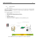
The SCM3712 reader board comes with an integrated USB interface, which also is used for the power
supply of the unit. Therefore only the USB interface needs to be connected. The drawing and the table
below are showing the exact Pin-Out of the USB connector.
5.1. USB Connector Pin-Out
Pin Number
Pin Name
Description
1
USB +5V
Supply Voltage
2
Data -
Data Line
3
Data +
Data Line
4
GND
Signal Ground
5
Shield
Connector for optional cable shielding
Table 5.1:USB Connector Pin-Out
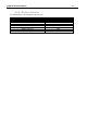
5.2. USB Connector Signal Min-/Max-Ratings
SCM3712 NFC, SCM3712 EA
Pin #
Min
Avg.
Max.
Comment
1
4.75V
5.0V
5.25V
USB DC Power
80 mA
90 mA
100 mA
2 3.0V 3.3 V 3.6 V
According to
USB 2.0 FS
3 3.0V 3.3 V 3.6 V
According to
USB 2.0 FS
4 - - - Signal Ground
5 - - - Signal Ground
Table 5.2: USB Connector Min-/Max Ratings, SCM3712 NFC & SCM3712 EA
SCM3712
Pin #
Min
Avg.
Max.
Comment
1
4.75V
5.0V
5.25V
USB DC Power
170 mA
185 mA
200 mA
2 3.0V 3.3 V 3.6 V
According to
USB 2.0 FS
3 3.0V 3.3 V 3.6 V
According to
USB 2.0 FS
4
-
-
-
Signal Ground
5
-
-
-
Signal Ground
Table 5.3: USB Connector Min-/Max Ratings, SCM3712
Please make sure the reader always is correctly connected. A wrong connection may prevent the
reader from working as expected or may even damage the reader. Defects caused by connection
errors are not covered by warranty regulations.