Series Laser Power/Energy Meters Setup and Operating Procedures Indicator Model No._____________ Serial No.
DETECTOR CALIBRATION DATA Calorimeter # 1: Model No: Serial No: Calibration Wavelength: Output Sensitivity (S): Time Constant (1/e): Calibration Temp: Sub. Heater Resistance (Rc): Sub. Heater Voltage (Vh): Sub. Heater Wattage (Wh): nm V/W sec. °C ohms volts watts Calorimeter # 2: Model No: Serial No: Calibration Wavelength: Output Sensitivity (S): Time Constant (1/e): Calibration Temp: Sub. Heater Resistance (Rc): Sub. Heater Voltage (Vh): Sub. Heater Wattage (Wh): nm V/W sec.
Thank you for choosing a Scientech laser power and energy measurement system. The Scientech employees are pleased to provide you with instruments designed and manufactured for years of reliable service. Please read this manual completely before using the equipment. This information will enable you to fully utilize the instruments. TABLE OF CONTENTS ASTRAL CALORIMETER SPECIFICATIONS: ...........................................................................................................................
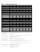
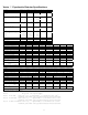
Astral Calorimeter Specifications: M odel Type A bsorber M ax Beam D iam eter SpectralResponse A verage Pow er(m ax) A verage Pow er(m in)* N oise Level Pow erD ensity (m ax) Peak Pow erD ensity (m ax) Single Pulse Energy (m ax) Energy D ensity (m ax) Precision A ccuracy Response Tim e D im ensions D xL (in.
Vector Pyroelectric Detector Specifications M o d el PH F 02 PH F 05 PH F 09 P 05 P 09 A c tiv e D ia m e te r 2 m m 5 m m 9 m m 5 m m 9 m m V o lta g e R e s p o n s e 3 .0 V / m J 0 .8 V / m J S ,I 1 5 V / m J 2 .5 V / m J 1 V / m J L .1 5 V / m J.0 2 5 V / m .0 1 V / m J E le c tric a l D e c a y T im e 2 .0 m s e c2 .0 m s e c (R C T im e C o n s ta n t) 0 .0 5 m s e c0 .0 5 m s e c0 .0 5 m s e c S I 0 .5 m s e c 0 .5 m s e c 0 .5 m s e c L 2 .5 m s e c 2 .5 m s e c 2 .
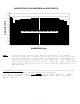
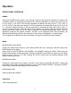
ABSORPTION OF HD ABSORBER vs WAVELENGTH 100 95 % ABSORPTION 90 85 80 75 CAUTION: SPECULAR REFLECTION 70 65 60 55 10600 2100 2000 1480 1300 850 1060 675 650 635 610 600 595 550 545 530 500 450 440 420 400 385 360 355 350 335 325 315 310 305 300 250 210 200 50 WAVELENGH [nm] NOTE: Please exercise caution when using HD detectors. They exhibit spectral reflection of between 7% and 33%, of the input power, back out of the aperture.
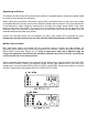
Unpacking and Setup The indicator and the sensor and accessories are packed in corrugated supports. All packing material should be saved for future damage free shipments. Before making any connections, verify that the power (VAC) requirement shown on the power entry module is compatible with the actual AC power outlet to which the indicator will be connected.
MODEL D200PC Any Scientech Vector pyroelectric sensor may be connected to channel A and any Scientech Astral calorimeter to channel B. The input switches on channel A should be configured per the previous instructions for the S200 and D200P set up. The interconnect cable for the calorimeter terminates with mini-DIN connectors. The "D" shaped connector shows the orientation for hook-up. MODEL D200C Both channels of the D200C are dedicated for use with any Astral calorimeters.
Operation FRONT PANEL CONTROLS RANGE Pressing the RANGE button begins a cycle through 6 ranges in the pyroelectric channel or 5 ranges in the calorimeter channel. In the pyroelectric channel if the 1 MΩ input impedance is selected the range cycle is 2 m, 20 m, 200 m, 2, 20, AUTO. If the 50Ω input impedance is selected, the range cycle is 2 µ, 20 µ, 200 µ, 2 m, 20 m, AUTO. In the calorimeter channel if a 25 mm calorimeter is connected the range cycle is 10 m, 100 m, 1, 10, AUTO (watts mode only).
Pressing the FUNCTION button begins the menu cycle of STATS, TUNE BAR, E, REMOTE (only if optional digital output is installed). Press the SELECT button when the desired function annunciator appears in the display. FUNCTION-Model D200P Pressing the FUNCTION button begins the menu cycle of CH AB RATIO, STATS TUNE BAR LOG E REMOTE, TRIG A TRIG B. Pressing SELECT when CH AB RATIO appears allows selection of channel A, channel B, the ratio of A/B or B/A.
SAVE Press the SAVE button to save the current setup to memory. This enables you to power cycle the indicator and return to the same indicator setup. The SAVE button must also be pressed after a calibration. OPERATING PROCEDURES Joulemeter sensor models P25, P50, SP25, SP50 P05,and P09 are coated with a special black absorbing material which provides a very flat spectral response over a broad wavelength band.
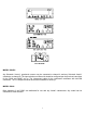
Remove the two slotted 4-40 binder head screws located on the underside of the detector. Pull off the outer housing to expose the battery. Remove the used battery from the battery holder and snap in the new battery. Slide the outer housing back in to place and secure with the screws. Figure 2 Do not touch the delicate pyroelectric crystals in the HR Series detectors. They should only be cleaned with a stream of clean air; nitrogen or CO2.
Calibration Calibration-MODELS S200, D200P Press the MODE button. When the CAL annunciator appears press the SELECT button. A menu of V/mJ, V/J, ATTEN will cycle. When calibrating for joulemeter sensor models P25, PHF25, SP25, SPHF25, P50, PHF50, SP50, and SPHF50, press the SELECT button when the V/J annunciator appears. Use the COUNT UP, COUNT DOWN buttons to enter into the display the V/J output sensitivity listed on the sensor ID tag. Press the SELECT button.
A portion of the beam would be measured by the transfer standard while the other portion is directed into the pyroelectric joulemeter. Select the average power mode by pressing the MODE button. Press the SELECT button when the mode annunciator appears. The menu will cycle through VOLTS, ENERGY, AVG ENERGY, and AVG POWER. Press the SELECT button when the avg power annunciator appears. Select the AUTO range by pressing the RANGE button. Press the SELECT button when the AUTO annunciator appears in the display.
The AVG ENERGY mode in the D200PC only exists in channel A - the pyroelectric channel. Power Mode Average Power Mode - Models S200, D200P, D200PC (channel A) Select the appropriate range for the average power level to be measured. The average power mode displays the average power (watts) of repetitively pulsed lasers Minimum rep rate of 10 pps). To enter into the average power mode, follow the same procedure as the energy mode except press the SELECT button when the AVG POWER annunciator appears.
(CH A), channel B (CH B), the ratio of channel A to channel B (RATIO A/B), or the ratio of channel B to channel A (RATIO B/A). Trigger Channel Selection: Press the FUNCTION button to begin the menu cycle. Press the SELECT button when the TRIG A TRIG B annunciator appears. A cycle of TRIG A, TRIG B will begin. Press the SELECT button when the desired trigger channel annunciator appears. If you are operating only one channel at a time, the trigger channel of the channel in operation must be selected.
Log Units of Measure When a dual channel indicator is being used as a ratiometer, log units of measure may be displayed. Use the FUNCTION button to start the menu cycles as described in the Function Menu Cycles section. Press the SELECT button when the LOG annunciator appears. Analog Output Pyroelectric Channels Analog output is accessible from the 50 ohm terminated BNC connector on the rear panel labeled Analog Output. The analog output is calibrated to 10 volts full scale on all ranges.
Calibration Using Electric Substitution Heating The electric substitution heating option must be ordered and installed at the factory when the calorimeter is purchased. It can not be retrofitted to a calorimeter at a later time. To calibrate using electric substitution heating proceed as follows. 1 Remove the screws holding the calorimeter’s ID tag and remove the plate to expose the circuit board. 2 Connect the calorimeter to the indicator, turn the power on and let the system equilibrate.
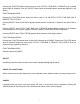
Figure 3 Operation of Astral Calorimeters with an Analog Chart Recorder Figure 4 Calorimeter Response The response of a calorimeter to a single pulse input as displayed by a chart recorder appears as in Figure 4.
1. Numerical Integration Finding the area under the curve in Figure 4 is the equivalent procedure for determining pulse energy. Choose an appropriate time interval, dt, and perform the summation: N N Σ Σ Vi E= Wixdt=(dt/S) i=1 i=1 The error caused by this procedure is: N Σ dE=(dt/S) dVi i=1 Σ The error, in theory, is only dependent upon the value of dVi, that is the cumulative random error of Vi. This number should approach zero if data is carefully taken.
F=E/Vp For the next pulse compute the total energy: E=F x Vp The error in using this method yields: dE=FdVp + VpdF The accuracy of this measurement depends upon the error in the original calibration, dF, and the error in the peak voltage dVp. A careful numerical integration yields a value for dF near zero. The value of dVp can be minimized by maintaining the geometry of the system (i.e. beam intensity, beam profile, wavelength and environment) during operation to be the same as during calibration.
front to back. Because the absorber (glass) is a poor conductor of heat, the same laser power density will produce a much higher surface temperature than it would produce on the surface absorber. Furthermore, the glass will confine the heat laterally while the surface absorber does not. The maximum power density for the volume absorber is nearly one tenth that of the surface absorber. If a repetitively pulsed laser is supplying a steady power input the situation is even more complicated.
Figure 7 20
REMOTE INTERFACE REMOTE INTERFACE FOR MODEL AD30 AND PYROELECTRIC JOULEMETER INDICATOR MODELS S200 AND D200P, D200PC, D200C These units have two remote interface options: RS232, or IEEE488. Units with one or both of these options may be operated remotely via the interface selected. The remote interface language is compatible with the IEEE488.2 standard, and provides complete access to all instrument functions.
If your instrument has both the RS232 and the IEEE488 interfaces installed, only one may be active at any given time. You can change the active interface from the front panel or from the remote interface itself. If the remote interface is the RS232 interface, and you wish to change it to the IEEE488 interface, you may enter the command "io ieee" from the RS232 interface. This command will change the instrument's saved interface choice.
As it comes from the factory, the configuration of the RS232 interface is 9600 baud, No Parity, No handshake. Should you desire to change this configuration, you can do it from either the front panel or the remote interface. Changing the setup from the front panel takes two steps: 1) Obtain the RS232 setup menu 2) Select the options desired Step 1) Obtaining the RS232 setup menu Proceed as described under FRONT PANEL SELECTION OF REMOTE INTERFACE. Once you have selected the RS232 interface, go on to Step 2.
Setting the handshake method to XON causes the instrument to cease transmission upon receipt of an XOFF character (ASCII 19, CONTROL-S), and to resume transmission upon receipt of an XON character (ASCII 17, CONTROL-Q). Care should be taken when setting the handshake method from an RS232 communications device, to insure that the device then begins using the handshake method chosen. IEEE488 INTERFACE When IEEE488 is selected, the front panel display is non-functional.
e) The IO command is coupled to the *RCL and the *RST command, in that it puts a new value into the saved value for the active remote interface. This means that the use of the IO command may cause the RS232 remote interface to become the active interface the next time the unit is powered up, or the *RCL0 or *RST command is executed. In the D200, the CAL,CAL?, ATTEN, ATTEN?, RANGE, and RANGE? commands operate on the channel selected by the SEL command.
zero. To save the current instrument state, the user issues the *SAV 0 command. To restore the saved state, the user may issue either the *RST or the *RCL 0 commands). The *LRN? query is not supported. (20) The self test instigated by the *TST? query checks the ROM checksum against the contents of ROM, and it does a non-destructive RAM test. 21) There are no status structures beyond those required by Std IEEE488.2. 22) There is only one overlapped command. That is the statistics gathering command COL.
Remote interface messages consist of zero or more commands or queries separated by semicolons and terminated by a linefeed (IEEE488) or a carriage return(RS232). A command or query consists of a command or query header followed by zero or more arguments separated by commas. cmd1 arg1;cmd2 arg1,arg2;cmdN arg1 Typical Remote Message Messages must be less than 75 characters. The queries RPT?, SND?, COL?, and *OPC?, and the commands COL and *OPC are intended to be placed as the last command in a message.
switch settings (on pyros), or the type of sensor plugged into the amplifier (AD30). The meaning of the integer is described further in specifications of the individual instruments. RANGE | auto automatic. Sets the range to the decimal number supplied, or makes range selection RPT? This query causes the remote interface to begin sending a sequence of comma-separated sequence of readings. A new reading is sent each time one is taken by the instrument.
*RST This is the ieee488.2 common command by the same name. When executed from the RS232 interface, it has the effect of restoring the saved instrument configuration. It has the additional function in the IEEE488 interface of forcing the interface into the OCIS state and the OQIS state. TUNE ON | OFF Turns the tune bar on or off. LIGHT ON | OFF Turns the LCD backlight on or off. MODE? Returns the instruments operating mode. The possible responses for the model AD30 are "ENERGY" and "AVGP".
ATTEN Sets the attenuation factor to apply in the calculation of energy or power. In the D200 this command applies to the channel selected by the SEL command. D200P, D200PC, D200C SPECIFIC COMMANDS DSP A | B | A/B | B/A This command tells the dual channel indicator what to display on the front panel. An argument of A means display readings from channel A in the front panel. A value of B/A tells it to display the ratio of the reading on channel B to the reading on channel A on the front panel.
31
IEEE488 SPECIFIC COMMANDS These commands may be used only from the IEEE488.2 interface. They are all members of the collection of so-called "common commands" described in the standard. *CLS Clears the Standard Event Status Register and forces the device into Operation Complete Command Idle state and Operation Complete Query Idle state. *ESR? Returns a decimal number which is the value of the Standard Event Status Register. Reading that register clears it.
Floating Point Display Mode (Normal vs Scientific): NORMAL Volts/Joule Channel A: 1.0 Volts/Joule Channel B: 1.0 Attenuation Factor Channel A: 1.0 Attenuation Factor Channel B: 1.
Mode of Operation: POWER MODE Backlight Switch: OFF Tune Bar Display: OFF Floating Point Display Mode (Normal vs Scientific): NORMAL Time Constant: 8.
MODEL S200 MENU TREES FUNCTION BUTTON STATS TUNE BAR E(Scientific Notation) REMOTE RS232(OPTIONAL) IEEE488(OPTIONAL) BUS ADDRESS BAUD RATE 300 600 1200 2400 4800 9600 PARITY HANDSHAKE XON CTS NONE EVEN ODD NONE MODE BUTTON CAL MODE V/J V/mJ ATTEN AVG POWER (Transfer cal in avg power mode VOLTS ENERGY AVG ENERGY AVG POWER RANGE BUTTON 1MΩ 50Ω 2µ 20µ 200µ 2m 20m AUTO 2m 20m 200m 2 20 AUTO 35
MODEL D200P MENU TREES FUNCTION BUTTON STATS TUNE BAR LOG E REMOTE TRIG A TRIG B CH AB RATIO STATS TUNE BAR LOG E(Scientific Notation) REMOTE TRIG A TRIG B RS232 CH A CH B RATIO A/B RATIO B/A IEEE488 BUS ADDRESS BAUD RATE 300 600 1200 2400 4800 9600 PARITY EVEN ODD NONE HANDSHAKE XON CTS NONE MODE BUTTON CAL MODE V/J V/mJ ATTEN AVG POWER (Transfer cal in avg power mode) VOLTS ENERGY AVG ENERGY AVG POWER RANGE BUTTON 1MΩ 50Ω 2µ 20 µ 20 0µ 2m 20m AUTO 2m 20m 200m 2 20 AUTO 36
MODEL D200PC MENU TREES FUNCTION BUTTON STATS TUNE BAR LOG E REMOTE CH AB RATIO STATS TUNE BAR LOG E(Scientific Notation) REMOTE CH A CH B RATIO A/B RATIO B/A RS232 IEEE488 BUS ADDRESS BAUD RATE 300 600 1200 2400 4800 9600 PARITY HANDSHAKE EVEN ODD NONE XON CTS NONE MODE BUTTON CHANNEL B CHANNEL A POWER CAL ENERGY MODE MODE CAL V/J V/mJ ATTEN AVG POWER (Transfer cal in avg power mode) VOLTS ENERGY AVG ENERGY AVG POWER RANGE BUTTON (Channel B) RANGE BUTTON (Channel A) 1MΩ 2m 20m 200m
MODEL D200C MENU TREES FUNCTION BUTTON STATS TUNE BAR LOG E REMOTE CH AB RATIO STATS TUNE BAR LOG E(Scientific Notation) REMOTE CH A CH B RATIO A/B RATIO B/A RS232 IEEE488 BUS ADDRESS BAUD RATE 300 600 1200 2400 4800 9600 PARITY HANDSHAKE EVEN ODD NONE XON CTS NONE MODE BUTTON POWER ENERGY MODE CAL RANGE BUTTON 25mm Calorimeter 10m 100m 1 10 AUTO 50mm Calorimeter Watts Only 38 300m 3 30 AUTO
Limited Warranty All Scientech Laser Power and Energy Measurement Systems are warranted against defects in materials and workmanship for two (2) years from date of delivery. During the warranty period, Scientech will repair, or at its option replace at no charge, components that prove to be defective. The equipment must be returned, shipping prepaid, to Scientech's product service facility.