Models H410 & H410D Laser Power and Energy Meters Setup and Operating Procedures Serial Number___________________ P/N 10795M
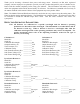
Thank you for choosing a Scientech laser power and energy meter. Scientech, an ISO 9001 registered company, and our employees are pleased to provide you with a product designed for years of reliable service. Please read this manual completely before using your indicator. This information will enable you to fully utilize the equipment and should be located nearby for reference. The indicator is intended to be used only in the manner outlined in this manual. Misuse of the equipment may cause product failure.
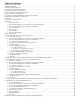
Table of Contents: Detector Operating Parameters: ................................................................................................................................................................. 2 CE Mark Certification: .............................................................................................................................................................................. 4 Environmental Requirements:.......................................................................
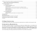
Calibration of Large Aperture Calorimeters Using Electric Substitution Heating:.................................................................................. 28 Calibration with an Interface Module and H410 Indicator:............................................................................................................. 28 Calibration without an Interface Module and H410 Indicator:........................................................................................................
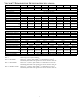
VECTOR™ H410 INDICATOR SPECIFICATIONS: Model Display Full Scale Ranges with Astral 25mm Calorimeter Full Scale Ranges with Astral 50mm Calorimeter Full Scale Ranges with Vector Pyroelectric Detector Full Scale Ranges with Photodiode Detector - Watts only Maximum Repetition Rate with Calorimeter in Joules Mode Maximum Repetition Rate with Calorimeter in Watts Mode Maximum Repetition Rate for Collecting Data in Statistics Mode with a Pyroelectric Detector Response Time with Calorimeter in Joules Mode Response
VECTOR™ PYROELECTRIC DETECTOR SPECIFICATIONS: Model Aperture Diameter Spectral Response Maximum Average Power Minimum Energy Noise Equivalent Energy Maximum Energy Density Accuracy Output Sensitivity Maximum Repetition Rate Maximum Pulse Duration Dimensions D x L - inches cm Weight - pounds/kgs Indicator Compatibility P 25 PHF 25 25.4 mm 25.4 mm .193-26µm PHD 25 PHDX 25 PHDX25UV SP 25 SPHF 25 SPHD 25 25.4 mm 7mm 7mm 25.4 mm 25.4 mm 25.4 mm .193-26µm .193-10.6µm .4-2µm .193-2µm .193-10.
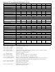
ASTRAL™ CALORIMETER SPECIFICATIONS: Model Type of Absorber Aperture Diameter Spectral Response Average Power Maximum Average Power Minimum Noise Level Maximum Power Density Maximum Peak Power Density Maximum Single Pulse Energy Maximum Energy Density Precision Accuracy Response Time Dimensions DxL - inches cm Weight - pounds/kg Indicator Compatibility Model Type Absorber Aperture Diameter Spectral Response Average Power Maximum Average Power Minimum Noise Level Maximum Power Density Maximum Peak Power Densi
LARGE APERTURE (100MM & 200MM) CALORIMETER SPECIFICATIONS: Model Type of Absorber Aperture Diameter Minimum Beam Diameter Spectral Response Maximum Average Power Minimum Average Power Noise Level Maximum Power Density Maximum Peak Power Density Maximum Single Pulse Energy Maximum Energy Density Precision Accuracy Response Time Dimensions DxL - inches/cm Weight - pounds/kgs Indicator Compatibility * This is a segmented absorber Note 1: 380401 Note 2: 384UV5, 388UV5 Note 3: 380801 Note 4: 380401 Note 5: 384UV
UNPACKING: The meter, detectors, and accessories are shipped in custom packing materials. All packing materials should be saved for future damage free shipments. If using the AC battery charger, verify that the electrical outlet is compatible with the charger. When using a charger, the H410 will operate with or without batteries installed. However, if batteries are installed, they must have a minimum charge of approximately 1 hour before the H410 will turn on, even if the AC battery charger is used.
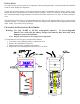
QUICK SETUP: Note: For detailed instructions for each type of detector, refer to the Operating Procedures section. 1. Turn On the Meter: Note: For the most accurate measurements possible, the H410 should be turned on and warmed up for 30 minutes. Slide the ON/OFF switch, located on the upper right side of the H410, to the ON position. The indicator will immediately turn on in the operational state last used.
The preceding list of modes in bold type represents the measurement modes of the H410. These modes are discussed in this Quick Setup section. The modes in normal type allow you to customize the H410’s set up for different detectors and are discussed in detail in the Operating Procedure section for each detector. Press the MODE button to start the menu cycle. Press the ON/SELECT button when the measurement mode you desire appears in the display. 7.
Slide the ON/OFF switch, located on the upper right side of the H410, to the ON position. The indicator will immediately turn on in the operational state last used. If you purchased the H410 with one detector, this detector’s operating parameters will be in the indicator’s memory and you are ready to take measurements. If you purchased more than one detector with the H410, you must make sure the operating parameters for the detector you plan to use are in the indicator’s memory.
H. Press the ON/SELECT button when “SPd” appears. Choose between “hF” for high frequency absorbers and “bL” for black coated absorbers according to the following chart. Type of Absorber Pyroelectric Detector Model Type Speed Selection Black Coated P, SP, PHD and SPHD bL High Frequency PHF and SPHF hF I. Press the ON/SELECT button to select the appropriate “SPd” setting. The indicator will return to the last operational state. J.
B. To Measure Average Energy (J AVG): Note: The maximum repetition rate for average energy is 300HZ. The average energy mode displays an average of a selectable number of pulses from 2 to 9999. i. Press the MODE button to start the menu cycle of J, AVG J, W, CAL and tO. ii. Press the ON/SELECT button when the AVG J annunciators appear on the display. The number of pulses to be averaged will now appear in the display. iii.
energy level to be measured. It is very important to select the most appropriate range. If you have selected a manual range and the laser pulse(s) has overflowed the maximum energy of the range, OF will be displayed when the data is recalled. You should then select a higher range. To enter into the statistics mode: A. Press the RANGE and MODE buttons simultaneously. The number of pulses in the last statistics run and a flashing SET annunciator will appear in the display. B.
B. Press the ON/SELECT button when the CAL annunciator appears. A second menu cycle of CAL 1, CAL 2, Attn and SPd will start. C. Press the ON/SELECT button when the CAL 2 annunciator appears. The average power (W) mode will automatically be selected and SET CAL will flash. D. Direct the laser beam through the calibrated beam splitter onto both the pyroelectric detector and the calorimeter transfer standard. E.
11. Time Out: Note: You must save all settings by pressing and holding the OFF/CANCEL button until the display blanks. If the H410 is turned off, by using the ON/OFF slide switch, before settings are saved they will be lost. Note: The time out default setting is 10 minutes. The time out feature conserves battery power by putting the H410 to sleep if there is no input from a detector after a selected period of time. To awaken the H410 once it is in the sleep mode press the ON/SELECT button.
USING THE H410 WITH ASTRAL SERIES OR LARGE APERTURE CALORIMETERS The calorimeter selected needs to be the appropriate model for the planned laser measurements. Please familiarize yourself with the operating specifications which are given in the front of this manual. Note: Astral and Large Aperture calorimeters are sensitive to all types of thermal input. Due to the handling of the calorimeter during setup and possible environmental temperature differences, thermal gradients may exist in the calorimeter.
To enter into the configuration mode: A. Press the MODE button. A menu cycle of J, W, CAL, tO and cd will begin. B. Press the ON/SELECT button when “CAL” appears. A menu cycle of tCon, SPd and Attn will begin. C. Press the ON/SELECT button when “tCon” appears. The current time constant value will be displayed and the “SET CAL” annunciator will flash. The time constant is a measure of the length of time the calorimeter takes to respond to a laser beam.
AC2500, AC25HD AC2501, AC25HD, AC2504 AC5000, AC50HD AC5001, AC50UV, AC5004 360401 with interface module 380401, 380402, 384UV5 with interface module 360801 with interface module 380801, 380802, 388UV5 with interface module 60 seconds 60 seconds 90 seconds 90 seconds 105 seconds 180 seconds 125 seconds 200 seconds Note: Make sure the calorimeter delay is less than the time out setting you will make in section 10. K. Press and hold the OFF/CANCEL button until the display blanks to save the settings. L.
A. To Measure Energy (J): Note: Calorimeters can only measure single shot energy pulses with the time between pulses dependent on the calorimeter delay setting from section 5J. With the calorimeter delay entered, the H410 will display the "trig" annunciator and the single pulse energy after the first pulse is delivered. The "trig" annunciator will then disappear after the calorimeter delay time has elapsed prompting you to fire another pulse.
C. Press the ON/SELECT button to enter the pulse population to memory. The display will blank and the STATS annunciator will flash. D. Press the MODE button to begin the run. The STATS annunciator will stop flashing and the indicator will automatically stop once the data has been collected. E. Press the ON/SELECT button to recall the data to the display one item at a time.
E. Press the ON/SELECT button. The attenuation factor is now active and the indicator will return to the last operational state. F. Press and hold the OFF/CANCEL until the display blanks to save the setting. G. Press the ON/SELECT button to turn the H410 back on. Attenuation factors can also be used to enable the H410 to display the correct reading when HD and HDX calorimeters are used with wavelengths other than their calibration wavelength. See the discussion at the beginning of this section for details.
USING THE H410 WITH ASTRAL PHOTODIODE DETECTORS: Be sure the photodiode detector is appropriate for the laser measurements you plan to make. Please familiarize yourself with the detector’s operation specifications before you use it. Note: Photodiode detectors can only be used to measure continuous wave lasers. 1. To Turn On the Meter: Note: For the most accurate measurements possible, the H410 should be turned on and warmed up for 30 minutes.
6. To Select a Wavelength: Note: You must save all settings by pressing and holding the OFF/CANCEL button until the display blanks. If the H410 is turned off, by using the ON/OFF slide switch, before settings are saved they will be lost. To enter into the wavelength selection mode: A. Press the MODE button. A menu cycle of W, CAL and Attn will begin. B. Press the ON/SELECT button when CAL appears. The current wavelength is displayed and the SET annunciator is flashing. C.
75% and reflects 25% of the beam. If the H410 is set up to measure the reflected beam the attenuation could be set up as follows: • An attenuation factor of 1 would display the value of the reflected beam. • An attenuation factor of 3 would display the value of the transmitted beam. • An attenuation factor of 4 would display the value of the source. To enter into the attenuation factor mode: A. Press the MODE button to start a menu cycle of W, CAL and Attn. B.
CALIBRATION OF ASTRAL CALORIMETERS USING ELECTRIC SUBSTITUTION HEATING: For Astral calorimeters the electric substitution heating option must be ordered and installed at the factory when the calorimeter is purchased. It can not be retrofitted to a calorimeter at a later time. To calibrate using electric substitution heating proceed as follows. Figure 4 A. Remove the screws holding the calorimeter's ID tag and remove the plate to expose the circuit board as shown in Figure 4. B.
CALIBRATION OF LARGE APERTURE CALORIMETERS USING ELECTRIC SUBSTITUTION HEATING: Electrical substitution heating is a standard feature of large aperture calorimeters. Figure 5 Calibration with an Interface Module and H410 Indicator: A. Connect a DVM to the white jacks of the calorimeter. Refer to Figure 5. B. Measure the resistance of the substitution heater making sure to subtract the resistance of the patch cables from the total resistance measurement.
Calibration without an Interface Module and H410 Indicator: Note: Whenever a large aperture calorimeter is used without an indicator the interface module is not used. For this procedure you will need to make an adapter cable to go from the calorimeter’s DIN connector to the DVM. The voltage output is on pin 1 of the DIN connector and should be connected to the positive side of the DVM. Ground is on pin 3 and should be connected to the negative side. Pin 2 is not used. Refer to Figure 5. A.
DETECTOR OPERATION WITHOUT AN INDICATOR: Pyroelectric Detectors: Standard and SP Models: Pyroelectric detectors can be operated with a 1MΩ input oscilloscope. The peak voltage shown on the oscilloscope can be divided by the V/J output sensitivity of the detector to calculate energy. Astral TM and Large Aperture Calorimeters: Cable Requirements: Astral calorimeters are powered up by the indicators.
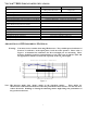
Operation of Astral and Large Aperture Calorimeters with an Analog Chart Recorder: Note: Whenever a large aperture calorimeter is used without an indicator the interface module is not used. Calorimeter Response: The response of a calorimeter to a single pulse input as displayed by a chart recorder appears below.
Initial Voltage Interpolation: A method used to eliminate the tedious numerical integration task is to project the thermal decay envelope on to the voltage axis, determine the 1/e decay time constant T, and estimate the total energy value (E): E = (Vo/S) x T The change from thermal absorption to thermal transport phenomena near the peak causes difficulty in accurately projecting the envelope on to the voltage axis introducing an error, dVo.
FACTORY RECALIBRATION: Scientech recommends that a complete calibration be performed annually to verify system accuracy. Please contact our Product Service Department at (800)525-0522 or (303)444-1361 or Fax (303)444-9229 or email inst@scientech-inc.com to arrange for a NIST traceable, factory calibration. LIMITED WARRANTY: All Scientech Laser Power and Energy Measurement Systems are warranted against defects in materials and workmanship for two (2) years from date of delivery.
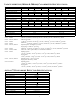
HD CALORIMETER AND PYROELECTRIC ABSORPTION VS. WAVELENGTH: Use this table for all HD calorimeters and HD pyroelectric detectors. Wavelength µm 0.200 0.210 0.220 0.230 0.240 0.250 0.255 0.260 0.265 0.270 0.275 0.280 0.285 0.290 0.295 0.300 0.305 0.310 0.315 0.320 0.325 0.330 0.335 0.340 0.345 0.350 0.355 0.360 0.365 0.370 0.375 0.380 0.385 0.390 0.395 0.400 0.405 0.410 0.415 0.420 0.425 0.430 0.435 0.440 0.445 0.450 0.455 0.460 0.465 0.470 0.475 Absorption % 93.66 93.78 92.18 90.44 88.79 90.07 90.42 90.
Wavelength µm 1.245 1.250 1.255 1.260 1.265 1.270 1.275 1.280 1.285 1.290 1.295 1.300 1.305 1.310 1.315 1.320 1.325 1.330 1.335 1.340 1.345 1.350 1.355 1.360 1.365 1.370 1.375 1.380 1.385 1.390 1.395 1.400 1.405 1.410 1.415 1.420 1.425 1.430 1.435 1.440 1.445 1.450 1.455 1.460 1.465 1.470 1.475 1.480 1.485 1.490 1.495 1.500 1.505 Absorption % 91.78 91.79 91.76 91.75 91.76 91.79 91.75 91.74 91.74 91.74 91.71 91.72 91.70 91.70 91.73 91.78 91.78 91.79 91.76 91.77 91.82 91.94 92.17 92.17 92.17 92.15 92.12 92.
Wavelength µm 2.129 2.130 2.132 2.135 2.136 2.139 2.140 2.143 2.145 2.146 2.150 2.153 2.155 2.157 2.160 2.161 2.164 2.165 2.168 2.170 2.171 2.175 2.179 2.180 2.182 2.185 2.186 2.190 2.193 2.195 2.197 2.200 2.201 2.205 2.208 2.210 2.212 2.215 2.216 2.220 2.224 2.225 2.227 2.230 2.231 2.235 2.239 2.240 2.243 2.245 2.247 2.250 2.251 Absorption % 90.76 90.41 90.05 90.41 90.43 90.84 90.48 90.46 91.65 90.04 90.45 90.44 90.42 90.39 90.36 90.69 90.76 90.43 90.44 90.44 90.41 90.38 90.38 90.37 90.40 90.44 90.42 90.
Wavelength µm 2.855 2.862 2.868 2.874 2.881 2.887 2.894 2.900 2.907 2.913 2.920 2.926 2.933 2.940 2.946 2.953 2.960 2.966 2.973 2.980 2.987 2.994 3.001 3.008 3.015 3.022 3.029 3.036 3.043 3.050 3.057 3.065 3.072 3.079 3.087 3.094 3.101 3.109 3.116 3.124 3.131 3.139 3.146 3.154 3.162 3.170 3.177 3.185 3.193 3.201 3.209 3.217 3.225 Absorption % 89.26 89.24 89.25 89.23 89.24 89.26 89.24 89.19 89.22 89.20 89.22 89.24 89.20 89.21 89.17 89.17 89.17 89.17 89.15 89.12 89.14 89.17 89.14 89.11 89.09 89.08 89.08 89.
Wavelength Absorption Wavelength Absorption Wavelength Absorption Wavelength µm % µm % µm % µm 5.357 86.95 6.682 86.05 8.879 84.32 13.09 5.379 86.95 6.717 86.06 8.940 84.27 13.23 5.401 86.94 6.752 86.07 9.002 84.22 13.36 5.424 86.90 6.787 86.00 9.065 84.17 13.50 5.447 86.89 6.823 85.91 9.129 84.11 13.65 5.470 86.86 6.859 85.86 9.194 84.06 13.79 5.493 86.86 6.895 85.91 9.260 84.00 13.94 5.516 86.86 6.932 85.93 9.326 83.95 14.09 5.540 86.83 6.970 85.92 9.394 83.90 14.25 5.564 86.80 7.007 85.91 9.462 83.83 14.
P MODEL PYROELECTRIC DETECTOR ABSORPTION VS. WAVELENGTH: Use this table for standard and slim profile painted (P) model pyroelectric detectors. Wavelength µm 0.30 0.40 0.50 0.60 0.70 0.80 0.90 1.00 1.10 1.20 1.30 1.40 Absorption % 96.850 96.850 96.850 96.850 96.850 96.850 96.850 96.850 96.850 96.850 96.309 95.768 Wavelength µm 1.50 1.60 1.70 1.80 1.90 2.00 2.00 2.10 2.20 2.39 3.00 3.42 Absorption % 94.931 94.094 94.094 94.094 93.209 92.323 92.323 91.831 91.339 89.092 86.542 86.032 39 Wavelength µm 4.
HF MODEL PYROELECTRIC DETECTOR ABSORPTION VS. WAVELENGTH: Use this table for standard and slim profile high frequency (HF) model pyroelectric detectors. Wavelength Absorption µm % 0.200 58.05 0.210 57.59 0.220 58.33 0.230 57.76 0.240 57.18 0.250 56.55 0.260 56.08 0.270 55.63 0.280 55.35 0.290 55.07 0.300 54.79 0.310 54.56 0.320 54.21 0.330 53.91 0.340 53.74 0.350 53.03 0.360 52.95 0.370 52.62 0.375 52.42 0.380 52.21 0.390 51.81 0.400 51.25 0.410 50.94 0.420 50.77 0.425 50.65 0.430 50.52 0.440 50.36 0.
Wavelength Absorption µm % 2.067 60.27 2.070 60.28 2.073 60.24 2.077 60.24 2.080 60.24 2.083 60.25 2.087 60.26 2.09 60.25 2.094 60.25 2.097 60.25 2.100 60.23 2.104 60.24 2.107 60.26 2.111 60.24 2.114 60.22 2.117 60.22 2.121 60.22 2.124 60.23 2.128 60.23 2.131 60.22 2.135 60.21 2.138 60.20 2.142 60.20 2.145 60.17 2.149 60.16 2.153 60.16 2.156 60.17 2.160 60.18 2.163 60.17 2.167 60.15 2.171 60.13 2.174 60.12 2.178 60.13 2.182 60.16 2.185 60.16 2.189 60.15 2.193 60.14 2.196 60.12 2.200 60.12 2.204 60.11 2.
Wavelength Absorption µm % 3.120 59.47 3.128 59.47 3.135 59.47 3.143 59.48 3.151 59.47 3.158 59.47 3.166 59.47 3.174 59.48 3.182 59.48 3.189 59.48 3.197 59.47 3.205 59.47 3.213 59.47 3.221 59.46 3.229 59.47 3.237 59.48 3.245 59.47 3.253 59.47 3.262 59.46 3.270 59.46 3.278 59.46 3.286 59.46 3.295 59.46 3.303 59.46 3.312 59.46 3.320 59.46 3.328 59.46 3.337 59.45 3.346 59.45 3.354 59.44 3.363 59.43 3.372 59.41 3.381 59.41 3.389 59.40 3.398 59.39 3.407 59.37 3.416 59.36 3.425 59.37 3.434 59.38 3.443 59.39 3.
Wavelength Absorption Wavelength Absorption Wavelength Absorption Wavelength Absorption µm % µm % µm % µm % 6.365 57.97 7.870 57.74 10.31 60.33 14.93 43.14 6.396 57.83 7.918 57.73 10.39 60.59 15.11 42.72 6.428 57.83 7.966 57.73 10.47 60.88 15.28 41.67 6.460 57.76 8.015 57.73 10.56 61.18 15.47 40.14 6.492 57.75 8.065 57.73 10.65 61.51 15.65 38.41 6.525 57.77 8.116 57.73 10.73 61.88 15.84 36.53 6.557 57.69 8.167 57.74 10.82 62.26 16.04 34.41 6.591 57.67 8.218 57.74 10.91 62.62 16.24 32.05 6.624 57.73 8.
SCHEMATICS: 44