
User's Manual


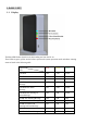
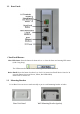

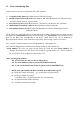
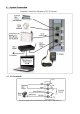

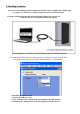

Table of Contents Page
INTRODUCTION
1, BASE UNIT
1.1 Display
1.2 Rear Panel
1.3 Mounting Bracket
1.4 Beeps & LED indication
1.5 Device Numbering Plan
2, System Connection
2.1 I/O Terminals
2.2 Home Automation Control Interface
2.3 RJ-45 Ethernet Interface
2.4 Power Input
2.5 Micro USB Interface
3, Working Scenario:
3.1 Works with HyperSecureLink software through USB port for local access.
3.2 Access the LS-10 by HyperSecureLink software or Mobile App. from local Intranet.
3.3 Works with HyperSecureLink software or Mobile App. from Internet.
3.4 Connects to a Cloud Server to Get Full Home Management Service from the Provider.
3.5 Connects to a Central Monitor Station to Get Alarm Service from the Service Provider.
4, Installation
4.1 Device Enroll
4.2 Placement of the Base Unit and Sensors
5, OPERATION MODE
5.1 AWAY Mode
5.2 HOME Mode
5.3 DISARM/ MONITOR Mode
5.4 Automatically Operation scheduling set by HyperSecureLink software.
5.5 Reaction of LS-10 to Burglar Alarm
5.6 Reaction of LS-10 to Other Alarms except Burglar Alarm
6. SYSTEM CHECK
6.1 Event Log
6.2 Device Status
7. HOME AUTOMATION CONTROL
8. CONTROL AND PARAMETER SETTINGS
8.1Control
8.2 Settings for Timers
8.3 Setting for Beep & Siren
8.4 Device Status Settings
8.5 Special Settings for Environment Sensor
8.6 Wire Sensor Input Settings
8.7 Switch On When Triggered
8.8 Switch Settings
8.9 MISC. Settings
8.10 CMS Settings
8.11 Scheduling
SPECIFICATIONS
APPENDIX
A. I/O Terminals
B: Partial Zone Control
C: How to Configure the Internet Parameters
D: Switch Action Table for Door Mag. and PIR
E: Load Factory Default of Internet Adaptor