
Specifications


www.meitavtec.com | info@meitavtec.com 8-9
Communication / B.M.S.
FMHC220-FC-MDB03 - Modbus RTU Protocol
Flush mount, 230VAC thermostat, for Fan Coil
B.M.S. applications, with Modbus protocol
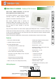
The FMHC220-FC-MDB03 is a highly versatile, stand alone
thermostat, suitable for Building Management System
application, with Modbus communication protocol.
With multiple, selectable modes of operation, the
FMHC220-FC-MDB03 offers suitability to 2-Pipe, 4-Pipe or
no valve Fan Coil system, electrical heating element option,
and can function as either Coo/Heat or Cool Only
thermostat.
Using DIP switch, technician can select between applying Auto-Change-Over sensor, or alternatively utilizing a
contact input for Economy mode to save energy. In addition, it offers the Auto-Fan feature to work at either Cool,
or Heat or at both. Additional features, such as Set Point Temp. Limits, Dead Zone and Room Temperature Offset
are all implemented and changeable.
Overall, the FMHC220-FC-MDB03 offers numerous options, nonetheless setting is simple and user friendly.
Features
y Flush mount, 230VAC thermostat
y 2 separate outputs for Cool & Heat
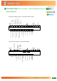
y DIP switch selectable options:
* Auto-Change-Over sensor or Contact input
* 2-pipe or 4-pipe system
* 1 or 3 fan speed control + Auto Speed
* With or without Auto-Change-Over mode
* Set point & room temp. display on LCD, or set point
temp. display only
* Always Auto-fan or Auto-fan selectable
* Internal or external temperature sensor
y Modes: Cool/ Heat / Auto- Change-Over/ Fan Only
y Contact input changes to Economy mode or
turns unit off (Optional)
y Cool Only thermostat – option
y Electrical heater - option
y Disable Fan operation – option (only in Cool,
only in Heat, or in both)
y Set point limits – 10…30°C
y 3 Auto-Fan types:
* Auto-fan in Cool & Heat
* Auto-fan only in Cool
* Auto-fan only in Heat
y Password for protected setting
y Pushbutton beeper – option
y Hand held remote control (RT03) - option
HEAT
SPEEDS
13
/
ECONOMY
°C
AUTO
CHANGE-OVER
EXT.
SENSOR
OPTION
AUTO FAN
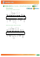
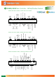
Wiring diagram