
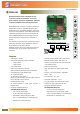
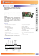
Specifications


www.meitavtec.com | info@meitavtec.com 5-2
Fan Coil Stand Alone Controllers
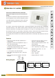
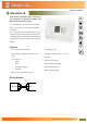
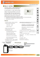
FMH220-P-FC-SUPER
Flush-mount, 220VAC thermostat, with 0-10V
proportional outputs for Fan-Coil valves and 3 Fan
speeds
The FMH220-P-FC-SUPER is a highly versatile thermostat for
Fan Coil applications. With numerous configuration options,
it is an ideal solution for wholesalers to keep on stock and
supply the proper configuration according to customer's
specifications.
This superior, energy saving thermostat offers 2 proportional outputs for Cool & Heat, with a configurable,
proportional opening. It also enables choosing various configuration options using DIP switches, to suit to
customer's requirements. For example, seller can configure it to a 2-Pipe or a 4-Pipe application, with or without
Auto-Change-Over mode, 1 or 3 fan speeds, or alternatively, internal / external sensor. Other important features,
such as Economy mode, temperature offset, dead zone and set point limits are also adjustable.
This versatility makes the FMH220-P-FC-SUPER the ultimate choice for comfortable, easy temperature control for
Fan-Coil.
Features
y Flush mount, 220VAC thermostat (available also in
110VAC model)
y Applicable for various Fan Coil applications: 2 pipe / 4
pipe – DIP switch selectable
y 2 separate proportional outputs for Cool and Heat
(configurable, proportional opening -0-10V)
y Auto change over sensor or contact input – DIP switch
selectable
y 1 or 3 fan speeds – DIP switch selectable
y With / without Auto-change-over mode – DIP switch
selectable
y Always Auto-Fan /Auto-Fan selectable – DIP switch
selectable
y Set point & room temp. display / set point
temp. only – DIP switch selectable
y Internal / External Temperature Sensor – DIP
switch selectable
y Hand held remote control – option
y Timer – ideal when you are asleep or away
y Adjustable set point limits - 10°…30°C
y Economy mode
y Lock buttons – option
y Offset – adjustable
y Beeping pushbuttons - optional
FC
COOL
HEAT
ECONOMY
OUTPUT
0-10V
SPEEDS
13
/
AUTO FAN
AUTO
CHANGE-OVER
TIMER
LOCK OPT.
°C
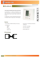
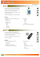
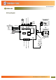
Wiring diagram
3 1 N2 L
Fan (3A)
High voltage wires
Heat valve
Cool valve
T1
0
External sensor (option)
T2
Contact input (remote switch) or Auto-change over sensor
4-Pipe configuration
One valve
2-Pipe configuration
No valve – fan only
Not connected
Not connected
(or)(or)
Y
0
W