RADIORANGER Wireless Fault Indication System Instruction Manual 20070301 *PM8300-01*
! CAUTION Equipment components are sensitive to electrostatic discharge (ESD). Undetectable permanent damage can result if you do not use proper ESD procedures. Ground yourself, your work surface, and this equipment before removing any cover from this equipment. If your facility is not equipped to work with these components, contact SEL about returning this device and related SEL equipment for service. ! DANGER Disconnect or de-energize all external connections before opening this device.
Table of Contents List of Tables ........................................................................................................... iii List of Figures...........................................................................................................v Preface ..................................................................................................................... vii Section 1: Introduction and Specifications Introduction .........................................................
This page intentionally left blank
List of Tables Table 3.1 Table 3.2 Table 3.3 Table 3.4 Table 3.5 Table 3.6 Table 4.1 Table 4.2 Table A.1 Table A.2 Date Code 20070301 Four Audio Modes Selectable With the DIP Switch Block...3.3 DIP Switch Settings...............................................................3.3 Duration of Audio Indications in Morse Code Mode............3.7 Duration of Audio Indications in Row/Column Mode ..........3.7 Complete List of SEL-8310 Audio Indications .....................3.
This page intentionally left blank
List of Figures Figure 1.1 Figure 2.1 Figure 2.2 Figure 2.3 Figure 2.4 Figure 2.5 Figure 3.1 Figure 3.2 Figure 3.3 Figure 3.4 Figure 3.5 Figure 3.6 Figure 3.7 Figure 3.8 Figure 3.9 Figure 3.10 Figure 3.11 Figure 3.12 Figure 3.13 Figure 3.14 Figure 3.15 Figure 3.16 Date Code 20070301 RADIORANGER System...................................................................1.2 SEL-8300 Wireless Interface ............................................................2.1 SEL-8300 Dimensional Diagram.................
This page intentionally left blank
Preface Manual Overview The RADIORANGER™ Instruction Manual describes how to install, operate, and troubleshoot the RADIORANGER Wireless Fault Indication System. An overview of each manual section and topics follows: Preface. Describes the manual organization and conventions used to present information. Section 1: Introduction and Specifications. Introduces the RADIORANGER system and lists specifications. Section 2: SEL-8300 Wireless Interface Installation.
viii Preface Manual Overview The page number appears at the outside edge of each page; a vertical bar separates the page number from the page title block. The page numbers of the RADIORANGER Instruction Manual are represented by the following building blocks: ➤ Section number ➤ Actual page number in the particular section The section title is at the top of the page title block, with the main subsection reference in bold type underneath the section title.
Section 1 Introduction and Specifications Introduction Locating faults in complex underground distribution systems has always proven challenging for electrical utilities. Troubleshooting often requires the time consuming and dangerous tasks of blocking traffic, opening, ventilating, draining, and accessing subsurface vaults in search of the fault location.
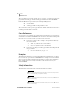
1.2 Introduction and Specifications Connections and System Diagram subsurface vaults. The RADIORANGER system can dramatically reduce fault-locating times in dense metropolitan areas, reduce troubleshooting costs, improve reliability, and improve personnel safety. Connections and System Diagram SEL fault indicators equipped with magnetic RADIORANGER Interface Probes communicate their status to the Wireless Interface.
Introduction and Specifications General Safety Information 1.3 General Safety Information FCC Statements This device complies with Part 15 of the FCC Rules. Operation is subject to the following two conditions: 1. This device may not cause harmful interference. 2. This device must accept any interference received, including interference that may cause undesired operation.
1.4 Introduction and Specifications Specifications Specifications Operating Temperature Range –40° to +85°C (–40° to +185°F) 5 to 95% humidity (noncondensing) Electromagnetic Compatibility Electrostatic Discharge Immunity: Radio Frequency Interference Immunity: Power Frequency Magnetic Field Immunity: Pulse Magnetic Field Immunity: Radiated Radio Frequency: (900 MHz and 1.
Introduction and Specifications Specifications Seismic (Quake Response): 1.5 IEC 60255-21-3: 1993 [EN 60255-21-3: 1995 + A1:1995] Severity Level: Class 2 IEC 60529: 2001 + CRDG:2003 [BS EN 60529:1992 Protection Class + REAF:2004] Severity Level: IP68 (4.
This page intentionally left blank
Section 2 SEL-8300 Wireless Interface Installation Introduction The SEL-8300 collects the status of up to 12 FCIs and communicates this data, upon request, to an SEL-8310 Remote Fault Reader. Connect SEL FCIs equipped with a magnetic probe output to the SEL-8300 via a keyed interface. Each magnetic probe assembly includes a permanent magnet, which activates a Hall-effect sensor inside the SEL-8300 to indicate the presence of an FCI probe, and two coils that deliver the FCI trip and reset signals.
2.2 SEL-8300 Wireless Interface Installation SEL-8300 Installation SEL-8300 Installation Securely mount the SEL-8300 using four 1/4 inch-sized (6.0 mm) fasteners (not included) designed for the surface to which the unit is being attached. To protect the polycarbonate material of the Wireless Interface, use a flat washer in conjunction with each fastener. We recommend that you install each fastener with a torque of 25 in/lbs not to exceed 50 in/lbs.
SEL-8300 Wireless Interface Installation SEL-8300 Installation 2.3 length is insufficient for optimal installation, order SEL-8300 units with an optional remote antenna that provides an extra 15' of lead length. For best results, orient the omni-directional antenna vertically so that it points toward the surface. Figure 2.3 SEL-8300 Installed in Underground Vault Power The SEL-8300 is equipped with two dials: a power switch and an ID selector.
2.4 SEL-8300 Wireless Interface Installation SEL FCI Connections i4147a Figure 2.4 SEL-8300 Informational Diagram SEL FCI Connections The interface portion of the SEL-8300 is equipped with 12 FCI magnetic probe interface ports aligned in a 4 x 3 matrix. The rows represent Ways (of a multiway switch) 1, 2, 3, and 4, as read from top to bottom. The columns represent Phases A, B, and C, as read from left to right.
SEL-8300 Wireless Interface Installation Testing and Verifying Installation 2.5 Clip to hold probe in place Permanent magnet to indicate installed probe Enlarged View of RADIORANGER Interface Probe SEL-8300 Wireless Interface Figure 2.5 Fault Circuit Indicator (FCI) The Wireless Interface Has 12 Magnetic Probe Ports Testing and Verifying Installation After installing the SEL-8300 Wireless Interface, test its operation and verify the communications range.
2.6 SEL-8300 Wireless Interface Installation Testing and Verifying Installation Step 7. If the range is not adequate, move the SEL-8300 to a different location, possibly a higher point in the vault. Step 8. If moving the SEL-8300 does not provide adequate communications range outside of the vault, you may need to order the SEL-8300 with an external antenna. You can mount the external antenna near the top of the vault.
Section 3 SEL-8310 Remote Fault Reader Operation Introduction The SEL-8310 Remote Fault Reader provides a human-machine-interface (HMI) to utility personnel charged with locating and isolating faulted sections of circuits. The SEL-8310 is a handheld device that communicates wirelessly with any SEL-8300 Wireless Interface within range. Flexible antenna Durable, buoyant case rated to IP54 Remote Fault Reader battery monitor Displays up to eight unique Wireless Interface IDs Easy-to-use keypad Figure 3.
3.2 SEL-8310 Remote Fault Reader Operation Power Requirements The SEL-8310 communicates the status of FCIs connected to any SEL-8300 within its range via LEDs and various audible tones. The front display section labeled Fault Indication has 12 LEDs arranged in a 4 x 3 matrix. The rows represent Ways 1, 2, 3, and 4, as read from top to bottom. The columns represent Phases A, B, and C, as read from left to right.
SEL-8310 Remote Fault Reader Operation DIP Switch Settings Table 3.1 3.3 Four Audio Modes Selectable With the DIP Switch Block Audio Mode DIP Switch 1 DIP Switch 2 Silent Mode ON ON Summary Mode ON OFF Morse Code Mode OFF ON Row/Column Mode OFF OFF The four audio modes are described briefly below. Refer to Audio Indication, for specific audio indications corresponding to each setting. Silent Mode—Annunciates Process Status and Button Press information only.
3.4 SEL-8310 Remote Fault Reader Operation Audio Indication Audio Indication The SEL-8310 is equipped with a piezospeaker that produces four distinct audible tones to supplement LED indications. The tones are denoted as pitches P1, P2, P3, and P4 in this manual and are annunciated for either a short (50 ms) or long (150 ms) duration. The tones or sequence of tones are depicted in Figure 3.2–Figure 3.14 and in Table 3.5.
SEL-8310 Remote Fault Reader Operation Audio Indication 3.5 P4 P3 P2 P1 Figure 3.4 Scan Initiate Audio Indication in All Audio Modes Scan Complete The Scan Complete event is annunciated after a scan has completed. This is the same tone sequence that plays at power-up. P4 P3 P2 P1 Figure 3.5 Scan Complete Audio Indication in All Audio Modes FCI Status Summary The FCI Status Summary tones provide feedback as to the status of the faulted circuit indicators connected to an SEL-8300 within range.
3.6 SEL-8310 Remote Fault Reader Operation Audio Indication FCI Status Summary—No Tripped FCI(s) The No Tripped FCI(s) status will be annunciated if the SEL-8310 receives valid data from an SEL-8300 with no tripped FCIs. This annunciation will occur following a press of the {Next} button, if the next ID contains no tripped FCI(s). As indicated in Figure 3.9 and Figure 3.10, the annunciation will vary for most audible modes. P4 P3 P2 P1 Figure 3.
SEL-8310 Remote Fault Reader Operation Audio Indication 3.7 Way 1 Way 2 Way 3 Way 4 Phase A Phase B Phase C Figure 3.12 Table 3.
3.8 SEL-8310 Remote Fault Reader Operation Audio Indication For example, in Row/Column Mode, the FCI Detail audio indication annunciated if Way 2 is the lowest Way containing a fault, and with Phases B and C faulted would be: Button Press The Button Press annunciation occurs under any of the following circumstances: ➤ Either the {Scan} or {Next} button is pressed in HMI Adjust Mode (see HMI Adjust Mode on page 3.
SEL-8310 Remote Fault Reader Operation Operation Table 3.5 3.
3.10 SEL-8310 Remote Fault Reader Operation Operation The POWER LED also indicates the relative battery life of the three 1.5 V (alkaline or rechargeable) AA batteries required to power the SEL-8310, as well as any internal RAM or Flash memory issues. ➤ A solid green LED indicates the voltage is above 3.2 Volts. ➤ A solid yellow LED indicates the voltage is at or below 3.2 Volts. ➤ A flashing red LED indicates that either the RAM or Flash memory self-check failed.
SEL-8310 Remote Fault Reader Operation Operation 3.11 When a scan is initiated, the SEL-8310 clears any previously acquired data. If the {Scan} button is pressed while a scan is in progress, the SEL-8310 aborts the current scan and clears all acquired data. The SEL-8310 tests the battery voltage at the start of each scan and updates the POWER LED as required. The scan sequence ends when one of the following occurs: ➤ A valid response is received for all eight wireless interface IDs.
3.12 SEL-8310 Remote Fault Reader Operation Operation LED Legend—Wireless Interface ID Section Green (solid) LED = Valid communication with an SEL-8300 set to the corresponding ID. All FCIs connected to that SEL-8300 are in the reset (unfaulted) position. Yellow (flashing) LED = The SEL-8300 (corresponding to the ID) is being represented in the Fault Indication section of the SEL-8310. Red (solid) LED = Valid communication with an SEL-8300 set to the corresponding ID.
SEL-8310 Remote Fault Reader Operation Operation Table 3.6 3.
3.14 SEL-8310 Remote Fault Reader Operation Operation correspond to speaker volume and LED intensity. The SEL-8310 will exit the HMI Adjust Mode five seconds after the last button press or after pressing and holding both the {Scan} and {Next} buttons simultaneously for one second. Following HMI Adjust Mode termination, the SEL-8310 reenters Normal Mode. The same data displayed prior to entering HMI Adjust Mode will be available.
Section 4 Testing and Troubleshooting Introduction This section provides guidelines for testing and troubleshooting the RADIORANGER system. Self-tests and troubleshooting procedures are included. Self-Tests The SEL-8300 and SEL-8310 perform periodic self-tests to verify proper operation. A self-test failure of either product is indicated via the Remote Fault Reader LED display. A flashing red POWER LED indicates an SEL-8310 self-test failure.
4.2 Testing and Troubleshooting Troubleshooting the SEL-8310 Table 4.1 Troubleshooting the SEL-8300 (Sheet 2 of 2) Issue Possible Cause/Response INTERFACE LED is flashing red on the SEL-8310 If the LED is flashing red during a collision (i.e., SEL-8310 is communicating with two SEL-8300 units), this indicates the SEL-8300 battery is weak. If the LED is flashing red without a collision, it indicates that a self-test has failed. Please consult the factory.
Testing and Troubleshooting Factory Assistance Table 4.2 4.3 Troubleshooting the SEL-8310 (Sheet 2 of 2) Issue Possible Cause/Response Audible annunciation contains a series of tones Device may be in Morse Code or Row/Column Mode. Check DIP switch settings on positions 1 and 2. Poor range between SEL-8300 and SEL-8310 Ensure the SEL-8300 antenna is unobstructed. Ensure the SEL-8310 is oriented properly (antenna is oriented vertically).
This page intentionally left blank
Appendix A Firmware and Manual Versions Firmware This manual covers the RADIORANGER system containing firmware bearing the firmware version numbers listed in Table A.1. This table also lists a description of modifications and the instruction manual date code that corresponds to firmware versions. The most recent firmware version is listed first. Table A.
A.2 Firmware and Manual Versions Instruction Manual Instruction Manual The date code at the bottom of each page of this manual reflects the creation or revision date. Table A.2 lists the instruction manual release dates and a description of modifications. The most recent instruction manual revisions are listed at the top. Table A.2 Instruction Manual Revision History Revision Date Summary of Revisions 20070320 Date of Initial Release.