INSTALLATION GUIDE Isodrive 1600 Revision V1 HOME APPLIANCES www.schweigen.com.
Index 1. Welcome _____________________________________________________________________________________________________ 3 2.
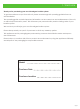
1. Welcome Thank you for purchasing your new Schweigen Isodrive system. To get the maximum output from this unit, please read through this operating guide before use and installation. The operating guide contains important information on the correct use and maintenance of the unit, as well as important safety notes. This will ensure your personal safety and the lasting value of your Isodrive system. We trust that you will enjoy your new Schweigen Isodrive system.
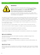
2. Your Safety WARNING Please read this section thoroughly before attempting to operate the appliance. Inspect your product upon receipt. Any damage or defects MUST be reported within 48 hours, or no claim will be recognised. DO NOT INSTALL THIS APPLIANCE IF YOU FIND IT DAMAGED. If this product is installed damaged, the supplier, nor the retailer, will be responsible for the costs associated with the repair, replacement, removal or re-installation of the appliances.
2. Your Safety This guide is for the installation of the Isodrive motor system after the canopy/rangehood or bathroom extraction grill has been mounted on the wall or ceiling. (Refer to canopy/rangehood or bathroom extraction unit installation manual). NOTE: All PVC pipe and flexi ducting measurements are referring to inside measurements, unless otherwise mentioned. Motor Features • Roof and wall mounting with IPX4 degree of weather protection. • Super quiet, long vane, backward curved centrifugal fan.
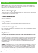
2. Your Safety NOTE: Although less than 5 to 6 metres will increase extraction power this will result in higher noise level. Maximum duct length 15 metres. Check with supplier if longer duct length is required. Do not reduce the duct size at any time and avoid sharp bends. Minimum Mounting Height This fan unit is intended for mounting at a minimum height of 2.1 metres (measured to the lower part of the fan impeller) above a floor or the ground.
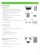
3. Description Isodrive Motor 1 2 3 4 5 6 i ii Included in the box: 1. Isodrive 1600 motor (405W x 220H mm approx.) Approx. 3 metre, 10amp cable and standard male plug 2. Fire resistant 150mm (160mm OD1) PVC riser pipe Note: Cable cut-out at the bottom end only 3. Flexible ducting Approx. 6 metres, 200mm (210mm OD1) diameter 4. Bell-mouth adopter ring 200mm duct to 150mm riser 5. Weather Shield Should be installed to prevent rain/water entering the unit 6.
4. Installation 1600 motor Weather shield attachment (only for 1600 motor) 50mm Pipe protrusion above dektite Power Cord 150mm PVC Pipe (Locking holes fan end) Dektite Fix fan module using side locking screw Fit side supports to locate pipe Strap to supports Bell-mouth Adaptor Connect to rangehood NOTE: Prevent any cord bunching by pulling cord through from plug top end Connect to power supply NOTE: Minimum ducting length 4 metres. Fully extend flexible ducting, cut to length.
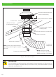
4. Installation Roof Installation Recommended duct length: 1600 motor — 5 to 6 metres. Mount 150mm (ISD) rigid PVC pipe securely to beams, trusses or other appropriate structures: refer figure 1. The pipe should be mounted vertically with the roof penetration being sealed using a Dektite or other appropriate sealing membrane or device. Ensure that the PVC pipe protrudes at least 50mm past the top of the Dektite, checking that the fan assembly clears the roof cladding at upper edge, refer figure 1.
4. Installation Wall Installation This type of installation is similar to roof mounting, ensuring that the pipe extends at least 50mm past the wall surface refer figure 2. If the pipe length is shortened, reproduce the power cord exit slot on the inside of the wall. IMPORTANT FOR 1600 MOTOR: Weather shield must be fitted to the top cover of the side flange using the 3 screws provided. Also, it is required to use the hanging bracket for wall mount installation, for more information please refer to page 15.
4. Installation IMPORTANT: When mounting pipe fan locking holes to be in outside end of pipe (fan end) Min 150mm long 150mm PVC pipe Bell-mouth Adaptor Weather shield upper most Locking holes at 10 and 4 o’clock Locking Screw Flexible 200mm ducting Min 50mm 1600 motor Cord slots at bottom (6 o’clock position) NOTE: Ensure that power cord is fed through exit slot and is not allowed to double back restricting fan inlet. Attach weather shield using 3 screws provided when wall mounting.
4. Installation Flat Roof Installation Flat roof mounting using optional mounting flange*.
4. Installation Installation Through Wall for Isodrive 1600 Due to the weight and to create stability for the Isodrive 1600 motor, it is require to use a hanging bracket. Warranty will be void if a hanging bracket is not used.
4. Installation Fan Unit Shutter Assembly for Isodrive 1600 1. Assemble by fitting shutter assembly into fan inlet shroud moulding, ensuring that attaching screws align with holes. Alignment can be checked visually by folding in shutter flaps. 2. Fully tighten both screws and re-check fitment into holes. 3. Fit assembly to duct pipe as per installation instructions supplied.
4. Installation Twin Motor Installation (suitable for the CL Range) Where two motors are to be used, follow the method below. Each motor should have a separate flue pipe. Refer figure 9. The two motors can be wired by an electrician. 1600 motor Z: Minimum distance between the two fans is 600mm. Z Must have separate flue pipe for twin fan installation Connect to rangehood Connect to motor Use smooth flowing curves for maximum airflow. Remove excess ducting by trimming to length.
4. Installation Twin Motor Installation Example Where two motors are to be used and there is only one 200mm outlet, follow the below methods for each motor then join into the “Y” piece prior to joining ducting to the canopy / rangehood. Refer figure 10.
4. Installation Twin 200mm Outlet Installation Example This is for use where one motor is to be used and there are two 200mm outlets, refer figure 11. 1600 motor 200 x 200 x 200mm If multi-fit Y joint supplied you will need to cut to size. Ensure flexible ducting is fully extended and as short as possible. Use smooth flowing curves for maximum air flow. Remove excess ducting by trimming to length.
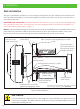
5. Measurements Measurements for Isodrive 1600 (Not to Scale) 405mm 148mm 220mm 190mm 90mm 35mm 225mm 440mm Dektite 160mm Shutter assembly is not shown in the diagram.
6. Flexible Duct 1. Flexible Ducting Flexible ducting must be fully extended and cut to the required length upon installation. Maximum fan performance will not be achieved unless the ducting is fully extended. Failure to fully extend ducting results in a smaller air passage and lower airflows. Incorrect installation may reduce airflow or increase noise levels. Call outs relating to incorrect installation will result in a service fee directed to the customer.
6. Flexible Duct 1. Shallow Roof Space In shallow roof spaces, do not crush or kink flexible ducting, as it will reduce air flow severely. 90 degree curve made of PVC or galvanise can be used as a substitute for the bend, refer to figure 12. 90 degree curve PVC or galvanise curve Figure 12 Important Note Please do not crush or kink flexible ducting, as it will reduce air flow and may cause noise to occur through the system. Ducting needs to be kept taut at all times.
6. Flexible Duct 1. Securing Flexible Duct Flexible duct must be installed with supports at maximum intervals of 1.5 metres. Flexible ductwork can be supported by using gaffer or electrical tape. Provided that it does not restrict the internal diameter of the ducting. Ducting installed looped over hanging beams should be installed in such a manner as to ensure the changes of direction are gradual. Support of the ducting with the use of hangers may be required, see option 2.
7.
7. Parts List 1. Parts List for Isodrive 1600 Number Part Number 1 P1120 P1120N Description Quantity M4X160mm Pan Head Screw 4 M4 KEPS Nut (not shown in figure) 4 5 P1114 Capacitor 3.
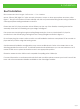
8. Maintenance 1. Roof Restoration or Cleaning Before doing your roof restoration or cleaning, please completely cover the outside motor system and avoid all chemical contact. IMPORANT Any damages caused by the use of chemical products are not covered by warranty.
9. Warranty/Disclaimer 1. Warranty (See warranty for more information) Isodrive motor has a 10-Year replacement product warranty. This is a change over warranty. The consumer is responsible for any charges associated with removal of the faulty unit and installation of the new unit. The customer is also responsible for any freight charges incurred in this change over process. Disclaimer Under our policy of continuous product development, product specifications may change without notice.
Notes 1.
Notes Page 27
HOME APPLIANCES Distributed by: Unit 102/45 Gilby Road, Mt Waverley 3149 Victoria. 1300 881 693 (EST) www.schweigen.com.