INSTALLATION / OWNER’S MANUAL Member of the International Schwank Group, Companies in: Germany, Netherlands, France, United Kingdom, Austria, Belgium, United States and Canada. Licensees Worldwide.
NOTICE: The Manufacturer reserves the right to make changes to equipment and specifications without obligation or notification. This publication, or parts thereof, may not be reproduced in any form, without prior written consent from The Manufacturer. Unauthorized use or distribution of this publication is strictly prohibited.
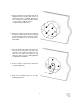
1. Control should be located away from direct radiant heat (also consider other sources of radiant heat such as sunlight, machinery, etc.). However the control should be able to 'see' the same conditions that the occupants will be experience. 2. Install a 4" octagon or a 4" pancake electrical box where control will be located (strongly recommended but not required). Position fixture mounting screws of electrical box horizontally. 3. Run 18/3 thermostat cable from the heater relay to the electrical box.
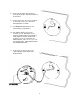
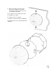
6. Insert cable through cable opening in TruTemp back plate. Attach back plate to electrical box. 8. Connect leads to 'R', 'W', and `C' terminals on TruTemp control. See attached wiring diagrams for details. 9. Set TEMPERATURE dial to the level desired during occupied times. 10. Turn LIGHT LEVEL knob counterclockwise to stop. With lights on (as would be during normal occupied times), slowly adjust the LIGHT LEVEL knob clockwise just to the point when the LIGHT indicator comes on.
12. Align control with the back plate and attach using supplied screws. Make sure that the occupancy sensor lense is in the top quadrant of the bulb. Note - Tamper proof screwdriver and screws are available as an option.
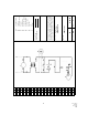
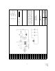
4 TruTemp Manual IM080326 RD: Aug 2006 RL: 3C KH Air Proving Switch Ignition Control Gas Valve Line Neutral IC GV L1 N 9 10 11 12 Field Control Wiring 15 ALL INFRA-RED HEATING EQUIPMENT & OPERATING 23 38 37 36 35 34 33 32 31 30 29 28 27 26 25 SUPERSEDE: DWN BY: DWG NUM: DWG NAME: N/A IH 608171a-I RL.: DATE: TruTemp / SINGLE STS 1 17/06/98 BLE CODES AND MANUFACTURER’S SPECIFICATIONS.
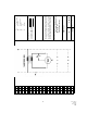
5 TruTemp Manual IM080326 RD: Aug 2006 RL: 3C KH Relay Coil Relay Contacts Heater Line Neutral RC R1 Ht L1 N 3 4 5 6 7 Line Voltage Field Wiring Low Voltage Field Wiring 11 12 14 ALL INFRA-RED HEATING EQUIPMENT & OPERATING 22 38 37 36 35 34 33 32 31 30 29 28 27 26 25 24 SUPERSEDE: DWN BY: DWG NUM: DWG NAME: 17/06/98 IH 608171c-I RL.: DATE: 1 11/08/98 TruTemp / Multiple STS / JM-0303-KT Transformer-Relay BLE CODES AND MANUFACTURER’S SPECIFICATIONS.
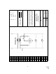
6 TruTemp Manual IM080326 RD: Aug 2006 RL: 3C KH Relay Coil Relay Contacts Heater Line Neutral RC R1 Ht L1 N 3 4 5 6 7 Line Voltage Field Wiring Low Voltage Field Wiring 11 12 14 ALL INFRA-RED HEATING EQUIPMENT & OPERATING 22 38 37 36 35 34 33 32 31 30 29 28 27 26 25 24 SUPERSEDE: DWN BY: DWG NUM: DWG NAME: 29/07/98 IH 608171d-I RL.: DATE: 2 11/08/98 TruTemp / STS Field Conversion/ JM-0300-XX BLE CODES AND MANUFACTURER’S SPECIFICATIONS.
7 TruTemp Manual IM080326 RD: Aug 2006 RL: 3C KH Relay Coil Air Proving Switch Heater RC AP HT 5 6 7 18 Transformer Heaters TRH 4 R1 Fan Motor FM 3 Line Voltage Field Wiring 11 ALL INFRA-RED HEATING EQUIPMENT & OPERATING 38 37 36 35 34 33 32 31 30 29 28 27 26 25 24 TRH 17 SUPERSEDE: DWN BY: DWG NUM: DWG NAME: 17/06/98 IH 608171a-I RL.: DATE: TruTemp / Multiple STS 1 13/08/98 BLE CODES AND MANUFACTURER’S SPECIFICATIONS.